The Spark 734 is an integrated tube amplifier manufactured by the Chinese company Zhuhai Spark Electronic Equipment, also known for its Cayin brand. This amplifier dates back to the late 1990s and early 2000s, a period when several Chinese manufacturers began offering serious tube amplifiers, featuring solid construction and fairly traditional circuit designs.
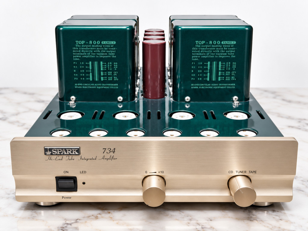
The 734 uses four EL34 output tubes in a class AB push-pull configuration, with a rated output power of 45 watts per channel into 8 ohms. The input and driver stages use 6922, ECC82 (12AU7), and 12BH7 tubes. It is a generously sized amplifier, weighing approximately 25 kg, with three large transformers clearly visible on top of the chassis.
On paper, then, this is a respectable amplifier, capable of delivering around 50 watts per channel and driving a wide variety of loudspeakers without particular difficulty. Unfortunately, the unit that arrived at my workshop was nowhere near performing as it should.
An amplifier that sounded terrible and didn’t get along with a Rotel CD player
The owner brought me this Spark 734 complaining about rather poor sound quality, but also about a much stranger problem: whenever the amplifier was connected to a Rotel CD player, it would start producing horrible noises through the speakers, even with the volume turned all the way down. With other sources connected, however, the problem apparently did not occur, and the amplifier seemed to work, although it still sounded terrible.
The owner’s request was therefore twofold: solve this mysterious incompatibility with the CD player and, since the amplifier was already on my workbench, investigate whether any modifications could be made to improve its sound quality. I started as I normally do, avoiding random component replacements and first trying to understand how the amplifier was actually operating.
The tubes were in perfect condition, but the power output was ridiculous!
The first thing I did was remove and test every single tube. The result was almost surprising: they were all in perfect condition, practically as good as new. No worn-out tubes, no insufficient emission, and no obvious problems that could explain the amplifier’s poor performance. I then reinstalled everything and began taking measurements with the amplifier powered up and connected to resistive dummy loads. And this is where the first unpleasant surprise appeared. One channel could deliver barely 6 watts, beyond which the waveform began to distort disastrously. The other channel performed only slightly better, without coming anywhere close to the power output one would expect.
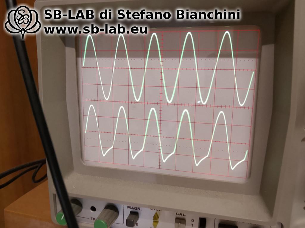
In short, for an amplifier rated at around 50 watts, managing to squeeze out only 6 watts or slightly more was hardly an impressive result! The problem was clearly somewhere in the circuitry, but without a schematic diagram available, figuring out where to look was not particularly easy. I began examining the various stages and checking their operation until, almost by chance, I noticed something rather suspicious. The two 12BH7 tubes, used to drive the EL34 output stage, were barely warm. This was rather strange, especially compared with the ECC82 tubes preceding them in the circuit, which were noticeably hotter. At that point, I checked the heater supply and discovered a rather serious wiring error.
A factory wiring error: the 12BH7 tubes were receiving the wrong heater voltage!
The 12BH7, just like the ECC8x family of tubes equipped with center-tapped heaters, can be powered in two different ways: at 12.6 volts, with the two heater sections connected in series, or at 6.3 volts, with the sections connected in parallel. Well, in this Spark 734, both 12BH7 tubes had been wired for 12.6-volt operation, but were actually receiving only 6.3 volts!
In practice, the heaters were receiving only half the voltage they needed. The tubes glowed very faintly, remained far too cold, and were absolutely incapable of providing the drive required by the EL34 output tubes to develop their full power. So this was not a case of worn-out or defective tubes, but an actual wiring error that prevented them from operating correctly.
I corrected the heater connections so that the 12BH7 tubes could operate properly from the available supply voltage and, during the next round of measurements, the amplifier finally began delivering its full power.
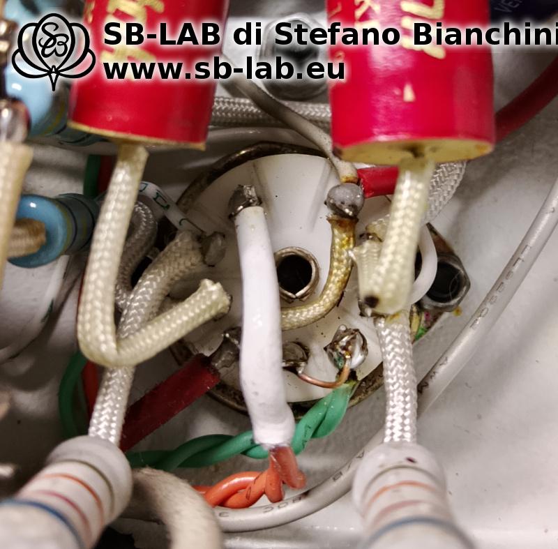
From just over 6 watts, we went to more than 50 watts per channel! Not exactly a minor difference. I wonder how long this amplifier had been operating under those conditions, and how such an error could possibly have gone unnoticed during manufacturing and final testing.
Improving negative feedback and damping factor
With the most serious problem solved, I moved on to evaluating the amplifier’s performance, looking for improvements that could be made without completely redesigning the circuit. The first thing I didn’t like was the damping factor, which measured just 5.
Such a value might be acceptable in a small 10-watt tube amplifier, but in a 50-watt amplifier I prefer something better. With this kind of output power, I believe it is advisable to achieve a damping factor of at least 7 to 8, in order to provide better control over the loudspeakers, particularly at low frequencies.
I therefore changed the value of the resistor in the negative feedback (NFB) network, appropriately increasing the amount of feedback. The result was a damping factor that increased from 5 to 7.6, a much more interesting figure. This modification also had another positive effect: it reduced the input sensitivity.
In its original configuration, the Spark 734 has excessively high input sensitivity, which makes much of the volume potentiometer’s travel practically unusable when the amplifier is connected to modern sources capable of delivering relatively high signal levels.
With the revised negative feedback arrangement, I therefore achieved two improvements at once: better loudspeaker control and a more reasonable overall gain. There is no reason to be afraid of negative feedback when it is applied correctly. The problem is not how much feedback is used in absolute terms, but how it is implemented and what results it actually produces in the circuit.
A few small modifications to the capacitors
I then carried out a few targeted modifications involving the electrolytic capacitors. In particular, I added polypropylene bypass capacitors across the two cathode electrolytics in the input stage, along with another bypass capacitor across the high-voltage power supply electrolytic that directly feeds the center taps of the output transformers (which I unfortunately forgot to photograph).
These are fairly minor modifications that do not require completely altering the amplifier or indiscriminately replacing components that are still working perfectly well. The idea is to improve the capacitors’ behavior at higher frequencies by adding film capacitors with different characteristics alongside the existing electrolytics.
The three mysterious trimmers inside the Spark 734
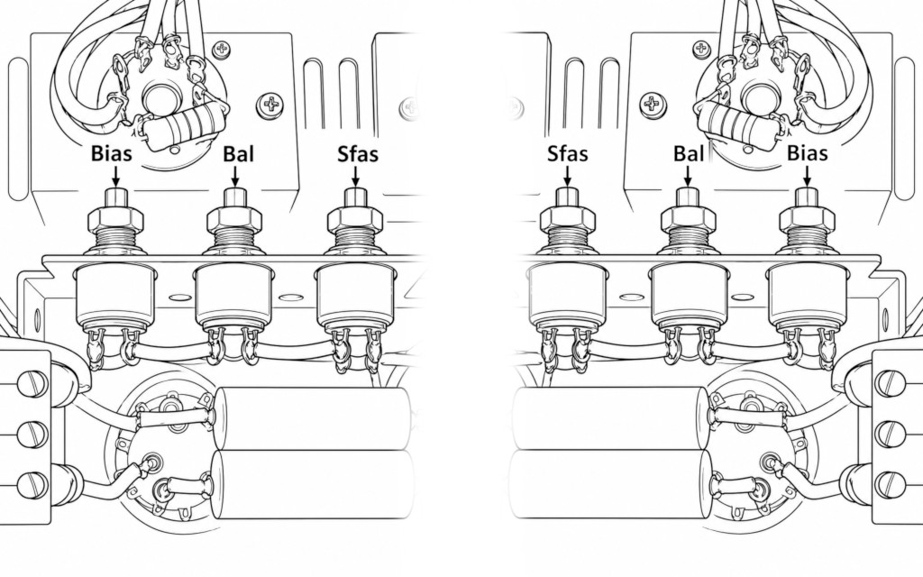
Another aspect worth discussing concerns the amplifier’s internal adjustments. The Spark 734 has three trimmers per channel, six in total. The problem is that the available documentation does not provide clear instructions on how to perform these adjustments and, at least in the unit I had on my workbench, the trimmers had actually been secured with thread-locking compound. Almost as if the manufacturer didn’t want anyone touching them!
After examining the circuit, I identified the function of each trimmer:
- Output tube idle current (bias) adjustment.
- Bias balancing between the two EL34 tubes in each channel.
- Phase splitter stage balancing.
Here I discovered another rather serious problem. While measuring the idle currents, I noticed that one channel was operating at almost twice the current of the other! And this was despite the four EL34 tubes being a selected and matched quartet. Such a situation is certainly far from ideal, both for the amplifier’s operation and for the lifespan of its output tubes.
Since there were no official instructions for the adjustment procedure, I had to spend some time studying the circuit, working out how the adjustments operated and checking their effects on the operating points and amplified signal. Once I understood how everything worked, I was able to set the idle currents correctly, balance the two output tubes in each channel, and properly adjust the phase splitters. Finally, both channels began behaving as they should.
In the following image, I have marked the position and function of the three trimmers found in each channel of the Spark 734, since this information does not appear to be clearly documented in the available manuals.
Of course, knowing where the trimmers are located does not mean that turning them randomly is a good idea. These adjustments require precise measurements and must be performed with the amplifier powered on, working in the presence of potentially lethal voltages.
And what about the problem with the Rotel CD player?
The interesting thing is that, once the operating problems had been corrected and the amplifier properly adjusted, the fault that occurred when connecting the Rotel CD player also disappeared.
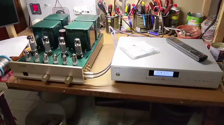
The amplifier now works normally with this source as well, without producing any of the horrible noises heard before, even with the volume turned down. The compatibility problem reported by the owner was therefore resolved without adding any extra circuitry or making specific modifications to the audio inputs. Evidently, the amplifier’s abnormal operation and badly incorrect adjustments were contributing to an unstable condition that became particularly noticeable with that source.
Final measurements
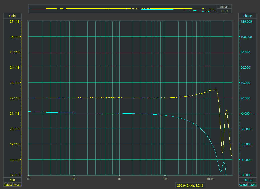
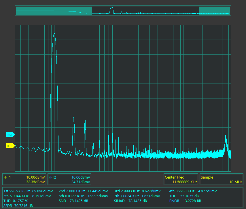
After completing the work, I subjected the Spark 734 to another series of instrumental tests. The final result was dramatically different from what I had measured when the amplifier first arrived at my workshop. The amplifier is now capable of delivering just over 50 watts per channel, with a damping factor of 7.6 and a very wide frequency response. The graphs recorded during testing show the amplifier’s performance after the repair and modifications.
Conclusions
This repair is a good example of just how important it is to measure an amplifier before deciding what to do to improve its sound. The owner had brought me a Spark 734 that sounded terrible and even appeared to be incompatible with a particular CD player. All the tubes were in perfect condition, yet the amplifier could only deliver a small fraction of its rated power. The main problem was not caused by the amplifier’s age or worn-out components, but by a wiring error in the 12BH7 heater connections, compounded by completely unbalanced bias settings. Once the fault had been corrected, the operating points properly adjusted, and a few targeted modifications made to the negative feedback network and capacitors, the Spark 734 finally showed what it was capable of.
What still puzzles me most is the heater wiring error: we are not talking about a minor adjustment issue or an aging component, but about two tubes that had been wired to receive 12.6 volts while actually receiving only 6.3. A rather crude mistake for an amplifier of this class. Now the Spark 734 delivers its full power, provides better loudspeaker control, has a more reasonable input sensitivity and, most importantly, works correctly even with the CD player that previously caused so much trouble. I’d say we’ve come a long way from those initial 6 watts!