The Luxman MQ-360 is a rather rare stereo tube power amplifier from Japanese production in the mid-1980s. Introduced in October 1985, it represents one of the models through which Luxman continued to keep its tube amplifier tradition alive at a time when the high-fidelity market was already dominated by transistor-based electronics.
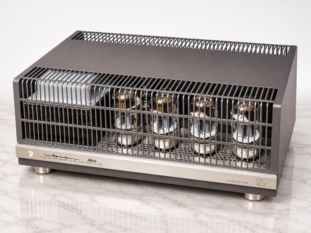
It was certainly not an inexpensive product: its Japanese retail price was an impressive 319,400 yen, a considerable sum at the time. The MQ-360 is a stereo power amplifier capable of delivering 40 watts per channel into 8 ohm, using a push-pull configuration with four 6550A output tubes, two per channel. The driver stage employs a pair of 6CG7 tubes, while two additional 12AU7A (ECC82) tubes complete the signal amplification section.
One particularly interesting feature is the choice of an automatic biasing system, or self-bias, combined with a circuit for balancing the output tube currents. The output transformers operate in an ultralinear configuration and were specifically designed for this circuit. Luxman also stated that the amplifier was designed to operate predominantly within the Class A region.
The published specifications include a frequency response from 10 Hz to 30 kHz within -1 dB, an input sensitivity of 1.1 volts, and a signal-to-noise ratio exceeding 100 dB. Everything is housed in a chassis featuring the characteristic Luxman appearance, with large transformers at the rear, prominently displayed tubes, and a protective metal cage. Its weight of approximately 19 kg also reflects the substantial magnetic components used in its construction.
The unit that arrived at my workshop is an original version intended for the Japanese domestic market, designed for a 100-volt mains supply rather than the 230 volts used in Italy. Naturally, this requires a suitable power supply arrangement during operation and testing.
The amplifier was shipped to me by a customer from Croatia, who reported a rather alarming fault: after a few minutes of operation, a sharp popping noise and a flash of light would occur inside the unit. What was supposed to be a repair involving a tube circuit, however, turned into a considerably more demanding job.
The first problem: completely inadequate packaging
When shipping a tube amplifier weighing almost 20 kg, proper packaging is essential. Simply surrounding it with seemingly sturdy materials and placing everything inside a box is not enough. Unfortunately, this Luxman had been packed using excessively rigid materials: hard polystyrene foam and thick cardboard, neither of which could effectively absorb impacts. This is a fairly common mistake. People assume that a harder material will provide better protection for a heavy object, when quite often the opposite is true.
Packaging must be able to absorb and dissipate impact energy through controlled deformation. If it is excessively rigid, mechanical shocks are transmitted almost directly to the contents. In this case, the result was disastrous.
During transport, the amplifier’s internal circuit board actually broke: We are not talking about a cracked solder joint or a small component coming loose, but an actual fracture of the printed circuit board, compromising both its mechanical integrity and its electrical connections.
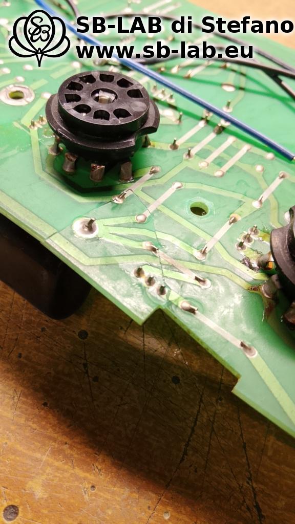
This is a particularly serious type of damage for equipment of this age, since finding an original replacement circuit board would be extremely difficult.
Rebuilding the circuit board with fiberglass and epoxy resin
Before I could even begin investigating the fault for which the amplifier had originally been sent, I had to concentrate on rebuilding the printed circuit board. In situations like this, simply bringing the two broken sections back together and repairing a few tracks with a soldering iron is not sufficient. The board must also regain adequate mechanical strength, otherwise subsequent vibrations and mechanical stresses could cause further damage.
I therefore reconstructed the damaged areas, reinforcing the structure with specially prepared fiberglass patches bonded using two-component epoxy resin. Fiberglass combined with epoxy resin creates a rigid, durable reinforcement capable of restoring the structural strength of the printed circuit board.
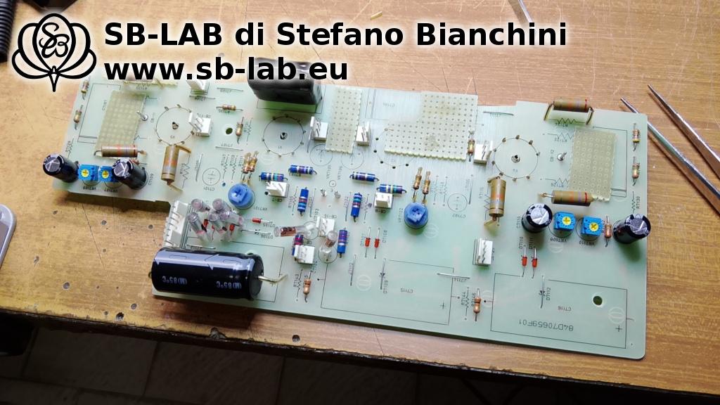
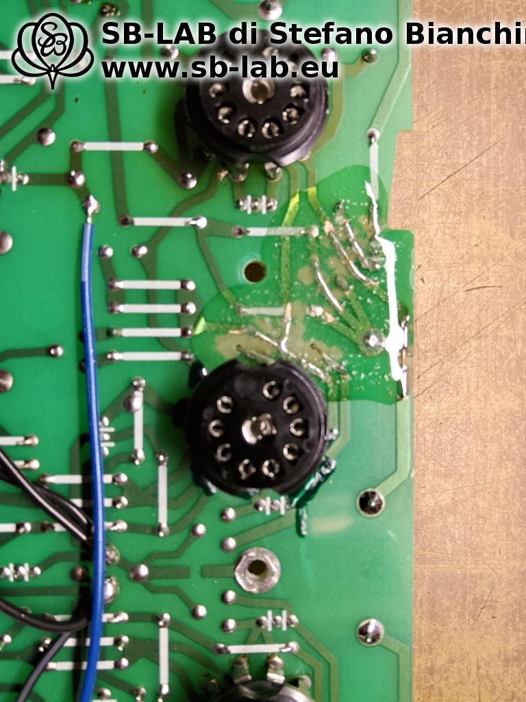
This repair required particular care because the board carries components exposed to high voltages and considerable thermal stress during normal amplifier operation. Only after restoring the mechanical structure and the damaged electrical connections was it possible to proceed with diagnosing the original fault.
The original fault: a burned resistor in the output stage
Finally turning to the problem reported by the owner, I identified a burned resistor in the circuit associated with one of the four output tubes. Further testing revealed that one of the four 6550 tubes was significantly more worn than the others.
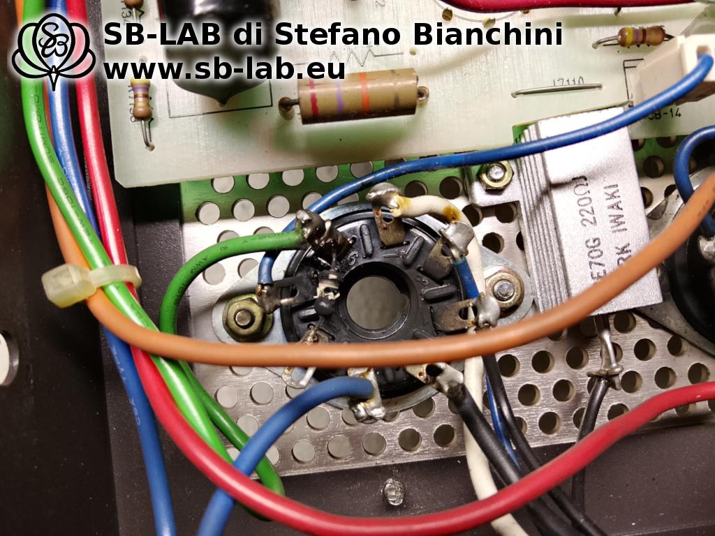
I believe it is likely that this tube, under certain operating conditions, developed abnormal behavior, possibly involving the onset of unwanted oscillations, causing an overload and the subsequent failure of the resistor.
This is a plausible reconstruction of the failure mechanism, not an oscillation that was directly observed during testing. Interestingly, however, a careful inspection of the area beneath the output tube sockets revealed further evidence of previous problems. Several resistors were of different types, clearly indicating replacements made during earlier repairs, and there were visible signs of scorching and overheating.
All these clues suggest that the amplifier had already suffered similar problems on several occasions. It therefore seems likely that someone in the past had simply replaced the burned resistors without fully identifying and eliminating the underlying cause of their failure. And this brings us to a particularly important detail.
The four bias trimmers: all perfectly centered!
The Luxman MQ-360 uses an automatic biasing system for its output tubes, but this certainly does not mean that no adjustments are required. The circuit includes four trimmers used to balance the idle currents of the output tubes. These controls make it possible to compensate for the inevitable differences between the electrical characteristics of individual tubes, allowing the push-pull output stages to operate in a more balanced manner.
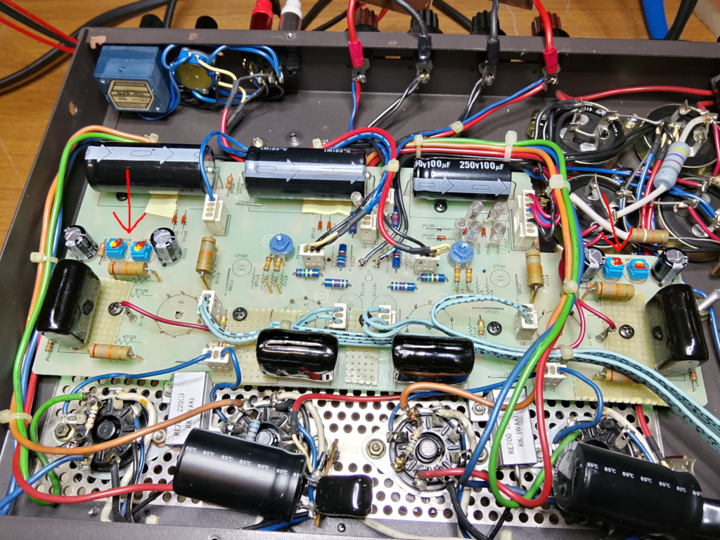
When I checked the amplifier’s adjustments, I discovered something rather curious: all four trimmers were positioned exactly at the midpoint of their adjustment range! A coincidence that was suspicious, to say the least.
The midpoint of a trimmer does not necessarily correspond to the correct setting. Its position depends on the characteristics of the tubes actually installed and must be determined through proper electrical measurements.
Finding all four controls perfectly centered suggests that someone had returned them to an arbitrary position without carrying out a proper calibration. Of course, it is impossible to establish exactly when this happened.
One important concept needs to be made clear: the fact that this amplifier uses self-bias does not eliminate the need to check the balance of the output tube currents. Tubes are not perfectly identical components, and their electrical characteristics can change significantly as they age.
In a circuit such as the Luxman MQ-360, replacing an output tube without checking its operating conditions and performing the necessary adjustments is a practice that can compromise the amplifier’s reliability.
Considering the previously replaced resistors, the signs of overheating, and the adjustment settings I found, I suspect that this amplifier had already undergone some less-than-careful repair work. I therefore proceeded to check and correctly adjust the balance of the output tube currents.
Checking the tubes: replace them all or keep those that are still in good condition?
Another important aspect of the repair involved testing the tubes. Let’s start with the two ECC82 tubes. Instrument testing showed that they were not particularly worn, but their electrical characteristics differed considerably from one another.
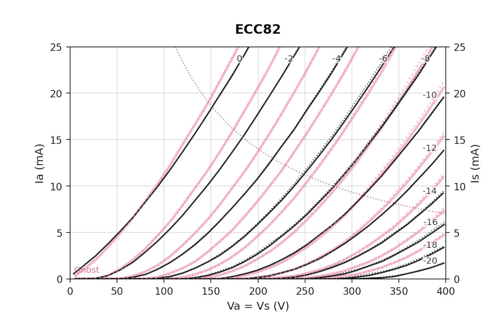
This kind of imbalance is undesirable in an amplifier using push-pull circuits, where symmetry between electrical characteristics is particularly important. I therefore replaced both ECC82 tubes with a carefully selected and electrically well-matched pair.
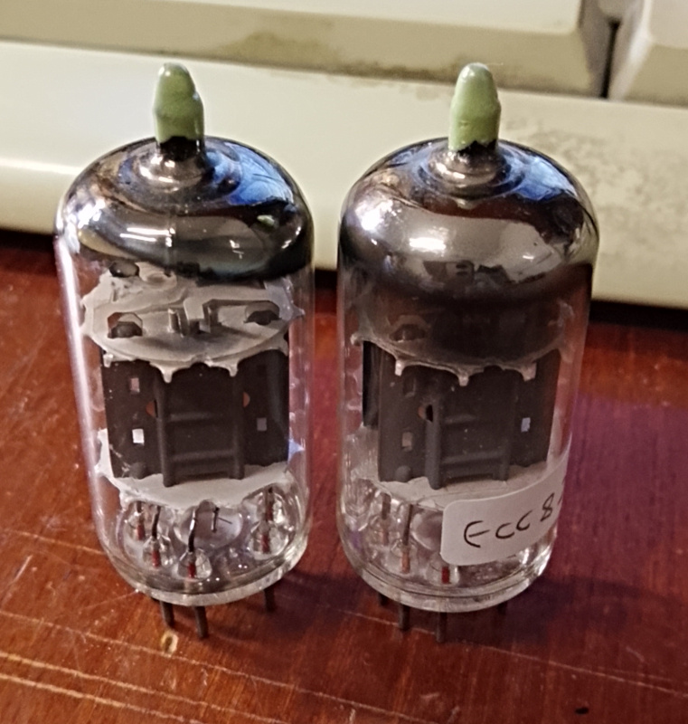
As for the output tubes, the situation was different. One of the four 6550 tubes was significantly more worn (and had probably suffered from screen grid overheating), while the other three still retained approximately 90% of their reference electrical characteristics.
In other words, three of the four tubes were still in excellent condition, and there was no technical reason to replace them. I therefore replaced only the defective 6550 with a used but perfectly efficient GE 6550, carefully selected through instrument measurements so that its electrical characteristics would match those of the three remaining tubes as closely as possible.
Some might argue that replacing the entire quartet would have been preferable. Personally, I disagree with this approach, at least when instrument testing makes it possible to identify an equally valid solution. A used tube is not necessarily a tube that should be discarded, just as a new tube is not automatically well matched to the others.
In this case, the most rational choice was to keep the three 6550 tubes that were still performing well, replace the defective one with an identical example that I happened to have available by sheer coincidence, and then carry out the necessary circuit adjustments. A targeted repair, without indiscriminate replacements or unnecessary expense.
Instrument measurements and performance after the repair
Once the repairs and necessary adjustments were completed, I subjected the Luxman MQ-360 to the usual instrument measurements to evaluate its actual performance. The amplifier achieved an output power of 37 watts RMS per channel, a result very close to the manufacturer’s specified 40 watts, especially considering the age of the amplifier and its output tubes. The measured damping factor (DF) was 5, while harmonic distortion was 0.2% at an output power of 1 watt.
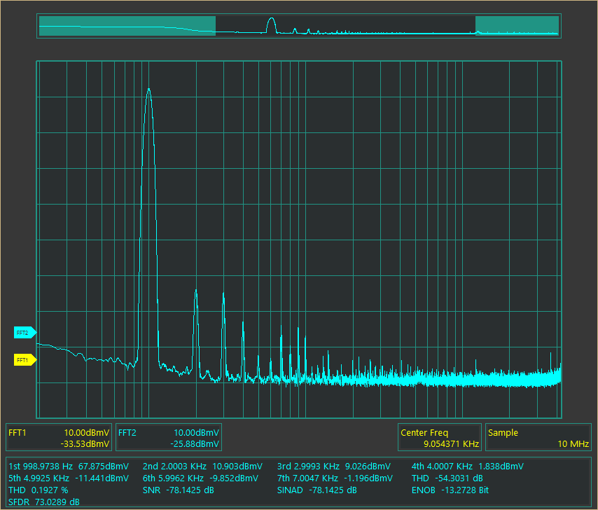
Particularly interesting was the frequency response measurement, performed with the selector switch in the DIRECT position: the amplifier demonstrated a frequency response extending from 10 Hz at 0 dB up to 80 kHz at -1 dB, far exceeding the manufacturer’s specified upper limit of 30 kHz.
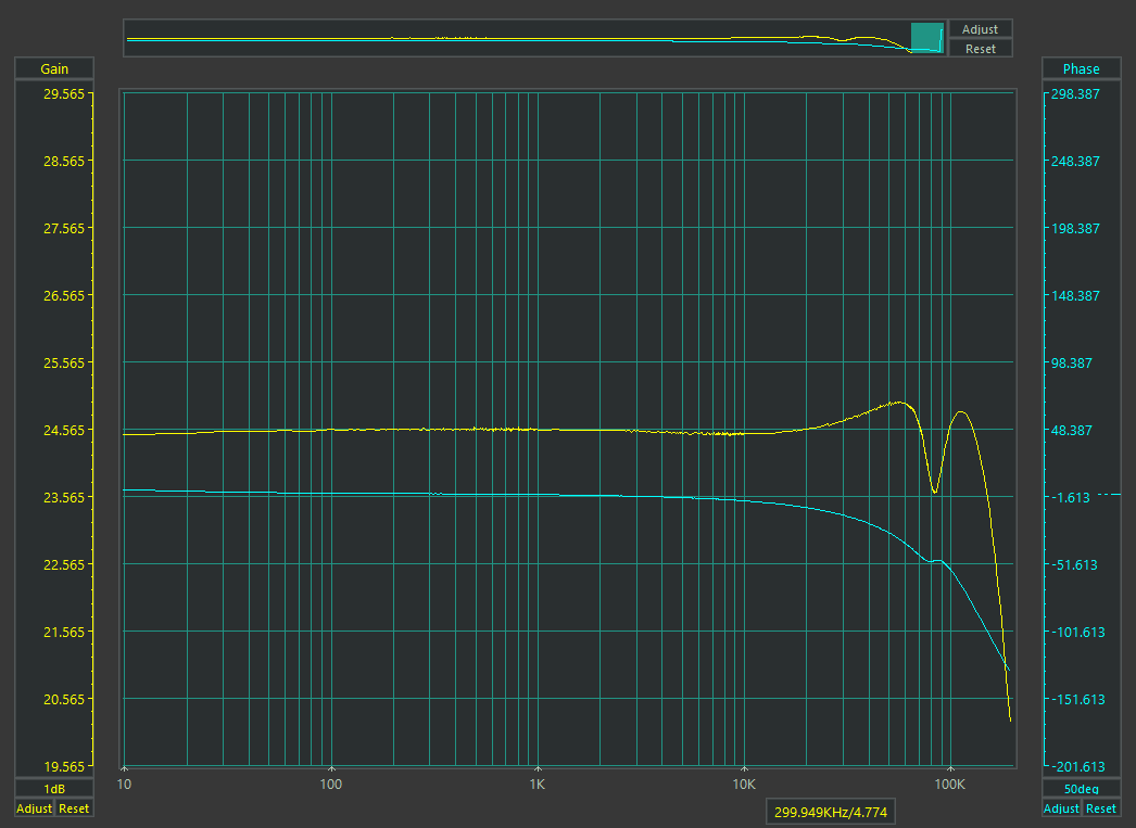
A decidedly impressive result for a tube power amplifier from 1985, confirming the quality of Luxman’s output transformers and demonstrating how equipment of this age, when properly repaired and adjusted, can still deliver highly respectable measured performance.
Restoring proper operation and final considerations
After rebuilding the circuit board, restoring the damaged components, replacing the necessary tubes, and adjusting the current balance, the Luxman MQ-360 returned to normal operation. This repair was particularly interesting because it highlighted two completely different problems. The first concerns transportation. A heavy and delicate tube amplifier cannot simply be shipped wedged between rigid packaging materials. Packaging that appears sturdy may prove completely ineffective at absorbing shocks and can even cause damage worse than the problems it was intended to prevent.
The fractured printed circuit board of this Luxman is a particularly clear example. The second issue concerns the maintenance of tube amplifiers. Replacing a burned resistor or plugging a new tube into its socket does not necessarily mean that an amplifier has been properly repaired.
It is essential to understand why a component failed, check the condition of the tubes, verify their biasing conditions, and make sure that every stage is operating correctly. It is rather amusing to see certain enthusiasts spending astronomical sums on incredibly expensive, selected, matched, and perhaps even blessed sets of tubes, only to plug them into their amplifiers without even picking up a multimeter or checking a single adjustment. As if the price of the tubes alone could guarantee that the amplifier will operate correctly! The reality is that even the most expensive matched quartet in the world, installed in a poorly adjusted circuit, can perform worse than four used but healthy tubes that have been properly tested and correctly biased.
The Luxman MQ-360 is an amplifier that deserves to be preserved and repaired with care, not only because of its relative rarity, but also because of its construction quality and the circuit solutions adopted by Luxman at a time when tube technology had become a deliberate design choice rather than a necessity. Another fascinating piece of Japanese high-fidelity history that can return to making music instead of unnecessarily ending up on the scrap heap.