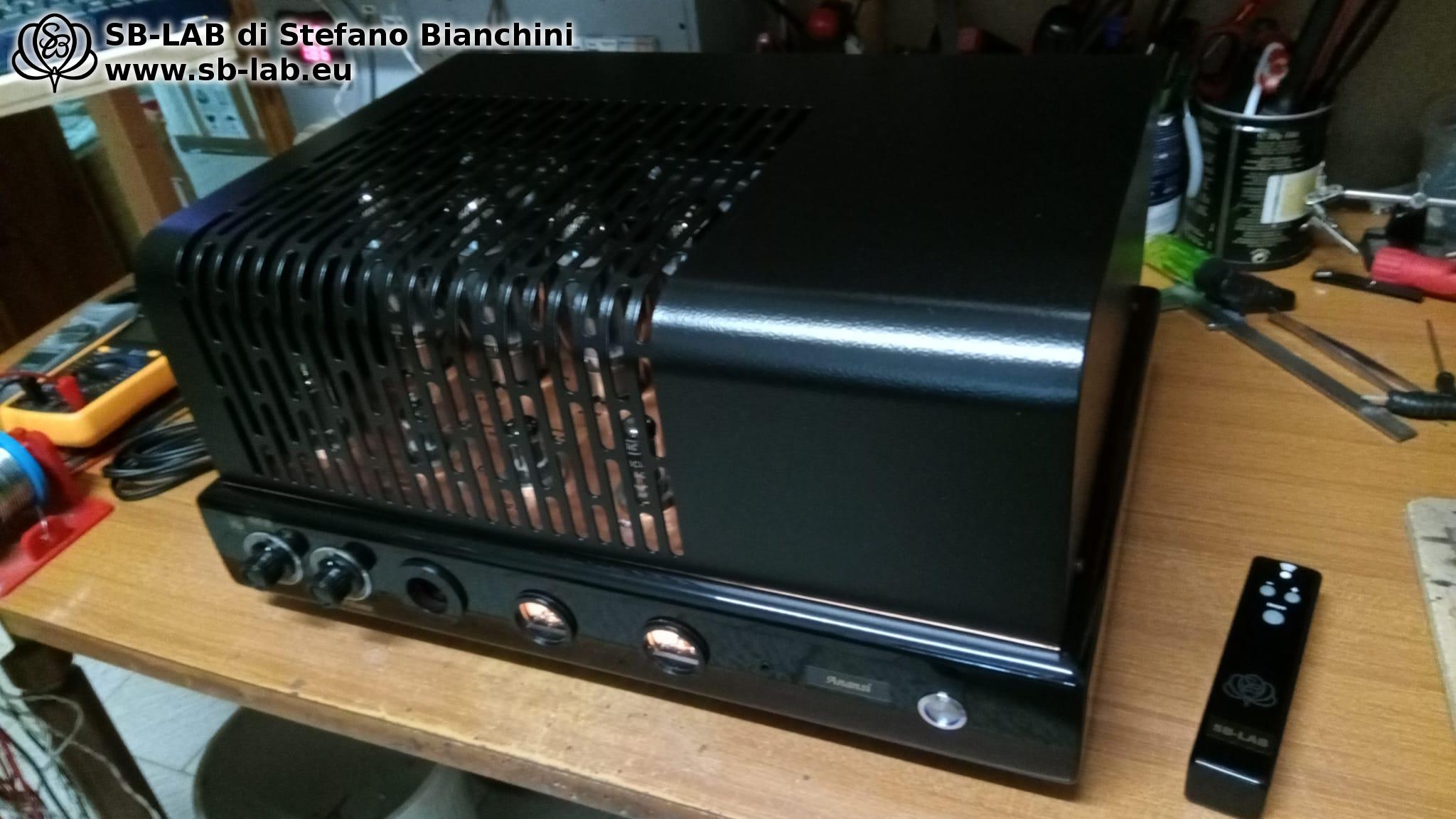
Nyx Aeterna – Single Ended with 2A3, the Twilight of the Stars, the Voice of Eternity

There is a moment in the life of stars when the glow of youth gives way to a subtler, more intense, and mysterious light. It is the moment of the white dwarf, an immortal remnant that keeps shining through the ages, a silent guardian of a stellar memory that does not fade. From this image comes Nyx Aeterna, my new single-ended tube amplifier, inspired by the Greek goddess of the night — Nyx, dark and majestic — and by the concept of eternity — Aeterna, like the light that still pulses from a fragment of a now-silent universe.

Nyx Aeterna is a tribute to pure sound, carved in the penumbra, wrapped in natural harmonics and timeless. A no-compromise project: 2A3 tubes in single-ended configuration for just 3.5 watts RMS of power, yet capable of sculpting every detail with grace and authority. The 6SL7 driver, with its warm, refined character, leads the whole apparatus like an invisible orchestra, while the vacuum rectifier — 5U4G or 5X4G — keeps the amplifier’s soul alive with a voltage that breathes like something ancient.

The sound? Silky, enveloping, twilight. Every note emerges naturally, as if floating in a timeless space, revealing nuances that conventional amplifiers only hint at. This isn’t about brute force, but intimacy — musical truth. It’s an experience to be heard in the dark, as one contemplates the starry sky: in silence, with respect.

Origins of Nyx Aeterna – From forgotten scrap to a new creature

Nyx Aeterna was born from what many would simply call “an old Chinese amp” — one of the many clones of the Single Ended Sun Audio SV2A3, like the Bowie SG-280SE or the Bowey 2A3C and similar others, sold in the past or even today on various bazaars for little money, now forgotten in dusty attics or damp basements. Abandoned objects, sometimes damaged, with slapdash circuits and cheap components. But with a chassis that, if desired, can become the foundation for something completely different.
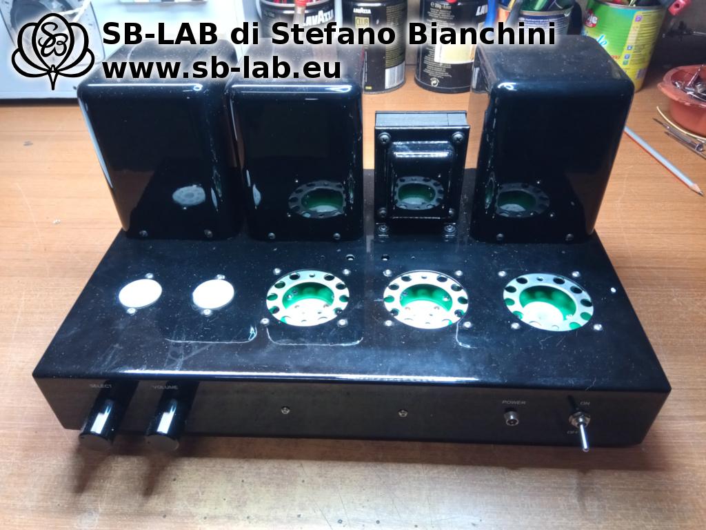
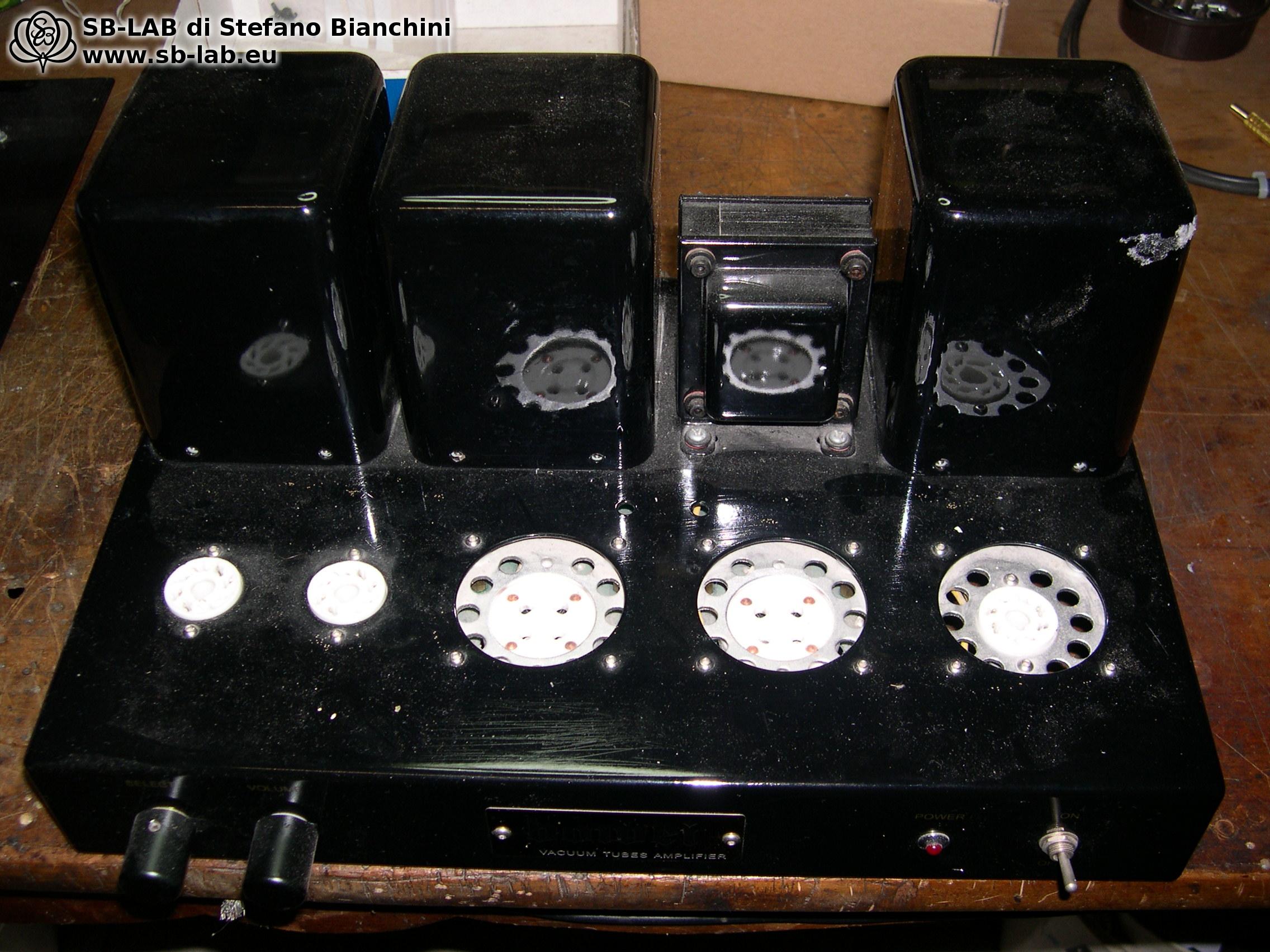
In my view, there’s only one sensible way to “modify” these amplifiers: start from scratch. We’re not talking about swapping a couple of resistors or a pair of capacitors and hoping for audiophile miracles. When I take them on, the changes are so radical that, in the end, only the shell remains. It’s a total reconstruction, not a restyling.

So does it make sense to buy such an amp on purpose and then rebuild it from the ground up? Probably not, if you have to pay for it. But if you already own one, or you pick it up for little, reusing at least the chassis and some mechanical parts can be a smart choice: the enclosure is ready, the holes are drilled, the tube sockets are mounted — and that’s a nice saving in time and money.

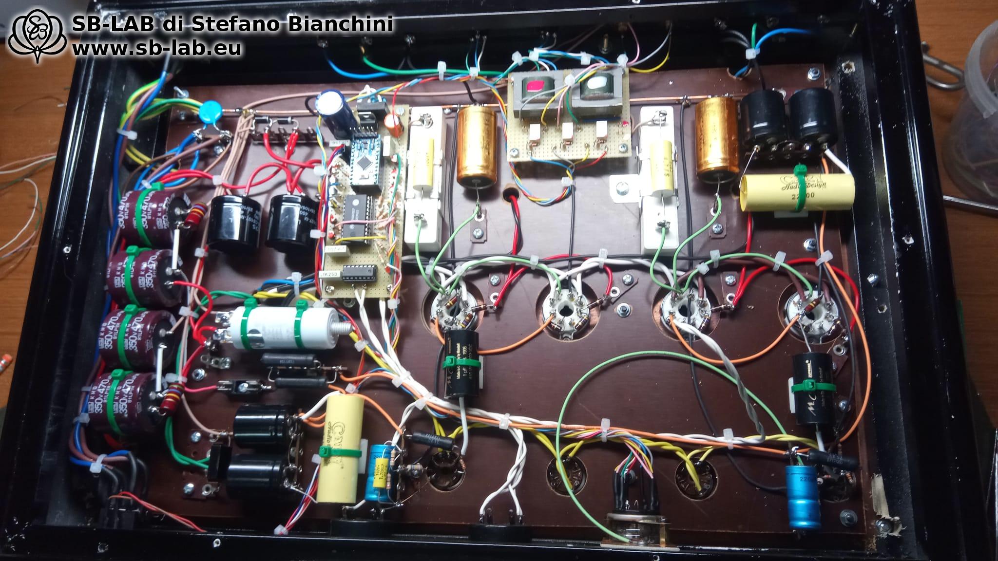
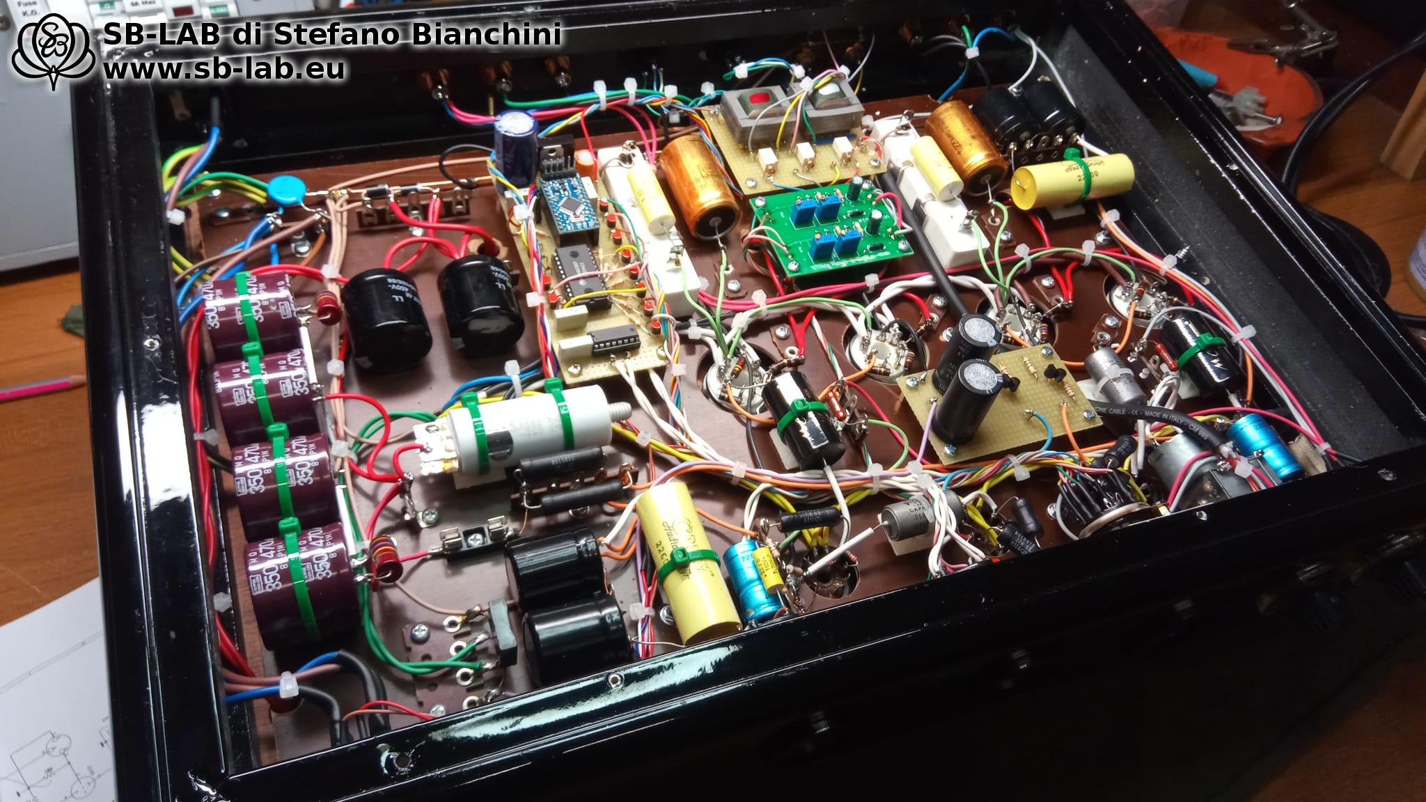
Nyx Aeterna was born exactly this way: not from an upgrade, but from an act of technical rebirth. It is not a Sun Audio clone, nor a variation on its theme. The circuit is completely new, designed from scratch around SB-LAB output and power transformers, chosen to enhance the 2A3’s tone and to ensure stability, silence, and dynamic coherence. The wiring has been entirely redone by hand, following high-level construction criteria, with no compromises.
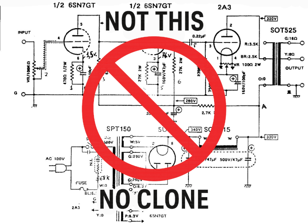
What began as a budget amplifier has been emptied, cleaned, and reassembled with a brand-new heart and soul. And today, Nyx Aeterna tells another story. Its own.

Disassemble, sandblast, be reborn

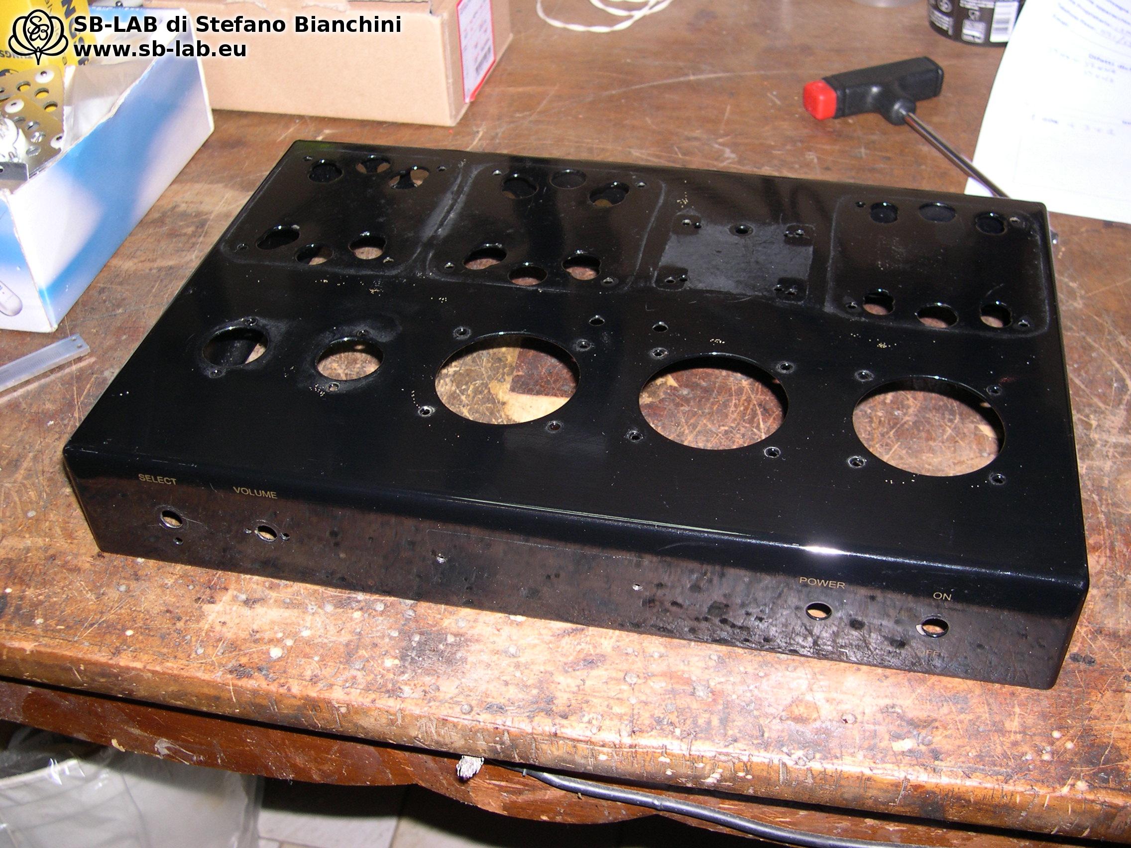
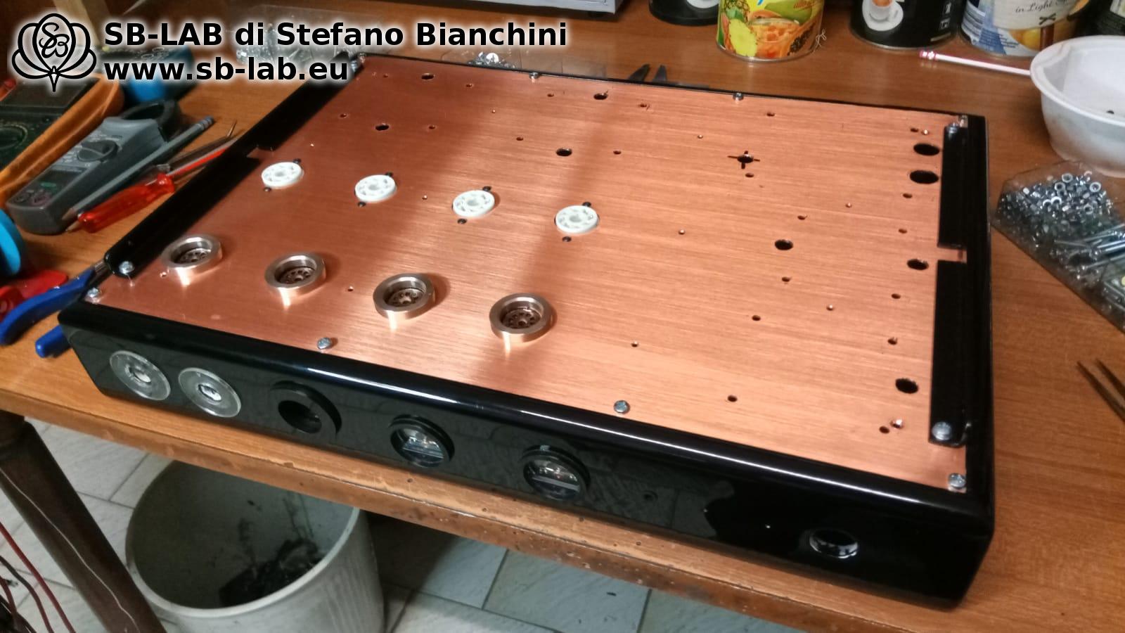
The first step was the most obvious: completely disassemble the starting amplifier. Screws, wires, sockets, components… everything removed until only the bare chassis remained, still bearing the marks of time. The original glossy paint of these devices, as often happens, was fragile and marred: deep scratches, indelible stains, dull halos, and in some spots even traces of rust beginning to creep out from under the finish. The classic fate of Chinese clones forgotten in some damp stairwell.

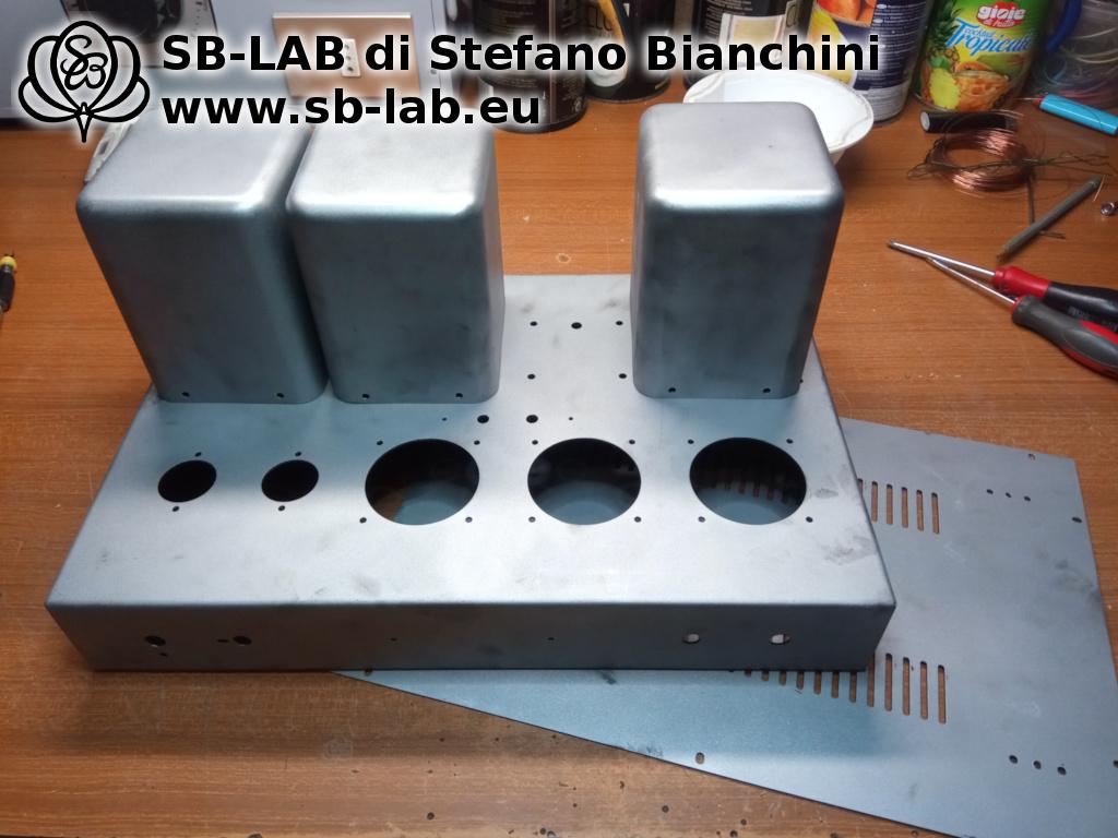
Before proceeding, I drilled a couple of additional holes to adapt the layout to my new circuit. Then, the chassis was sandblasted, to achieve a complete stripping and, above all, a slightly rough surface — ideal for giving grip to the new powder coating. The final result is a black, orange-peel effect finish, much more robust, scratch-resistant, and with a look that is both technical and elegant.
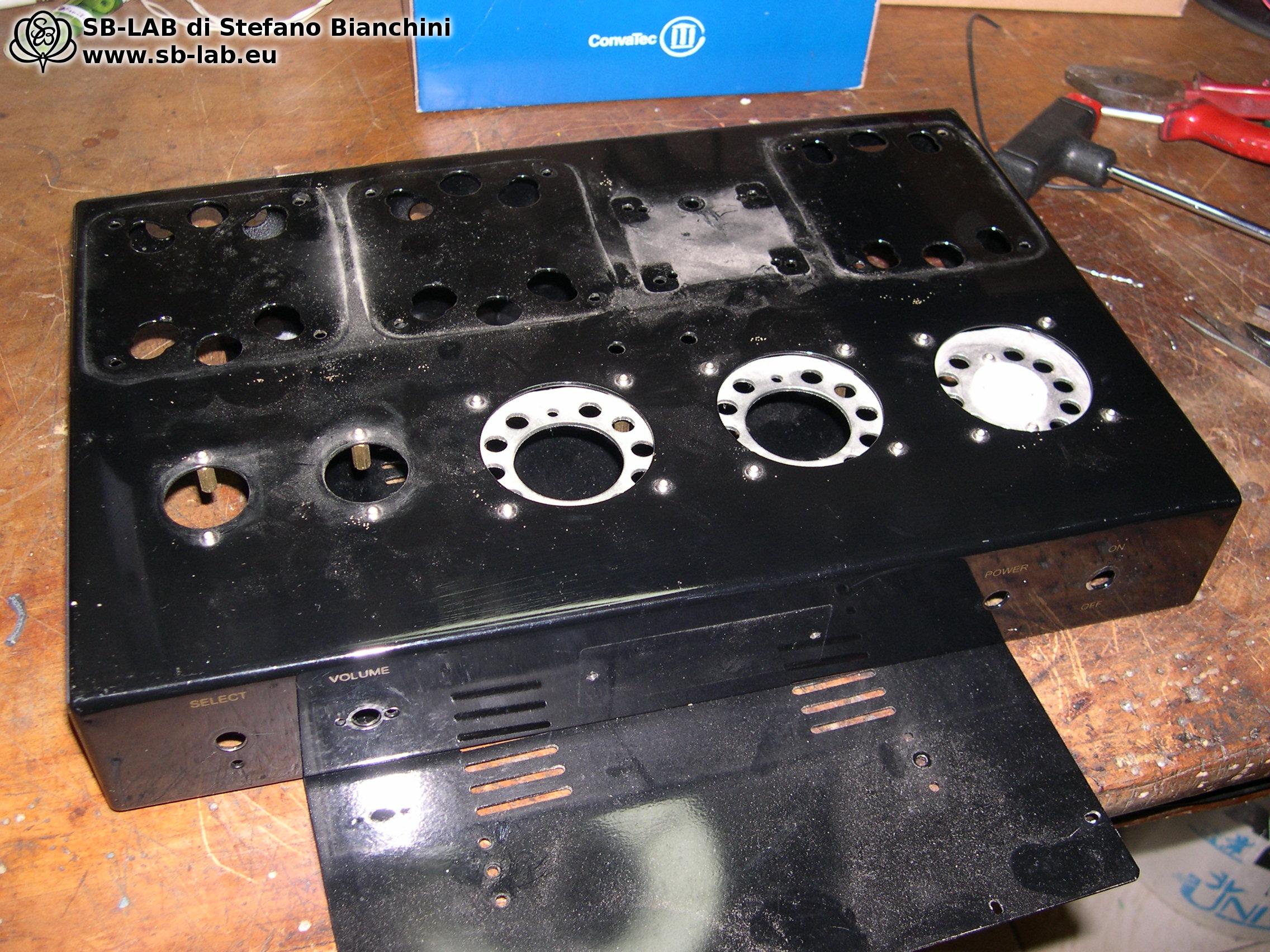
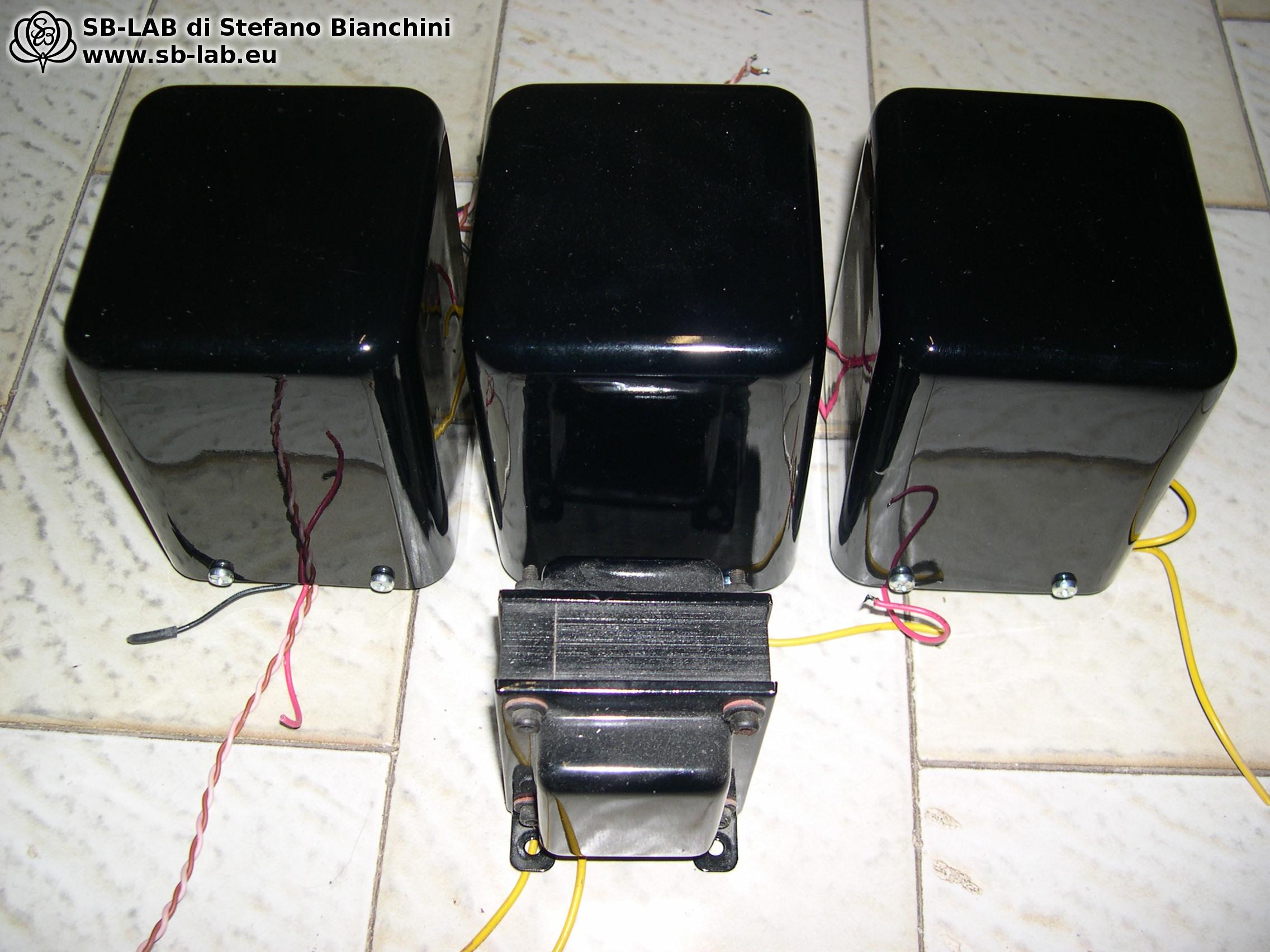
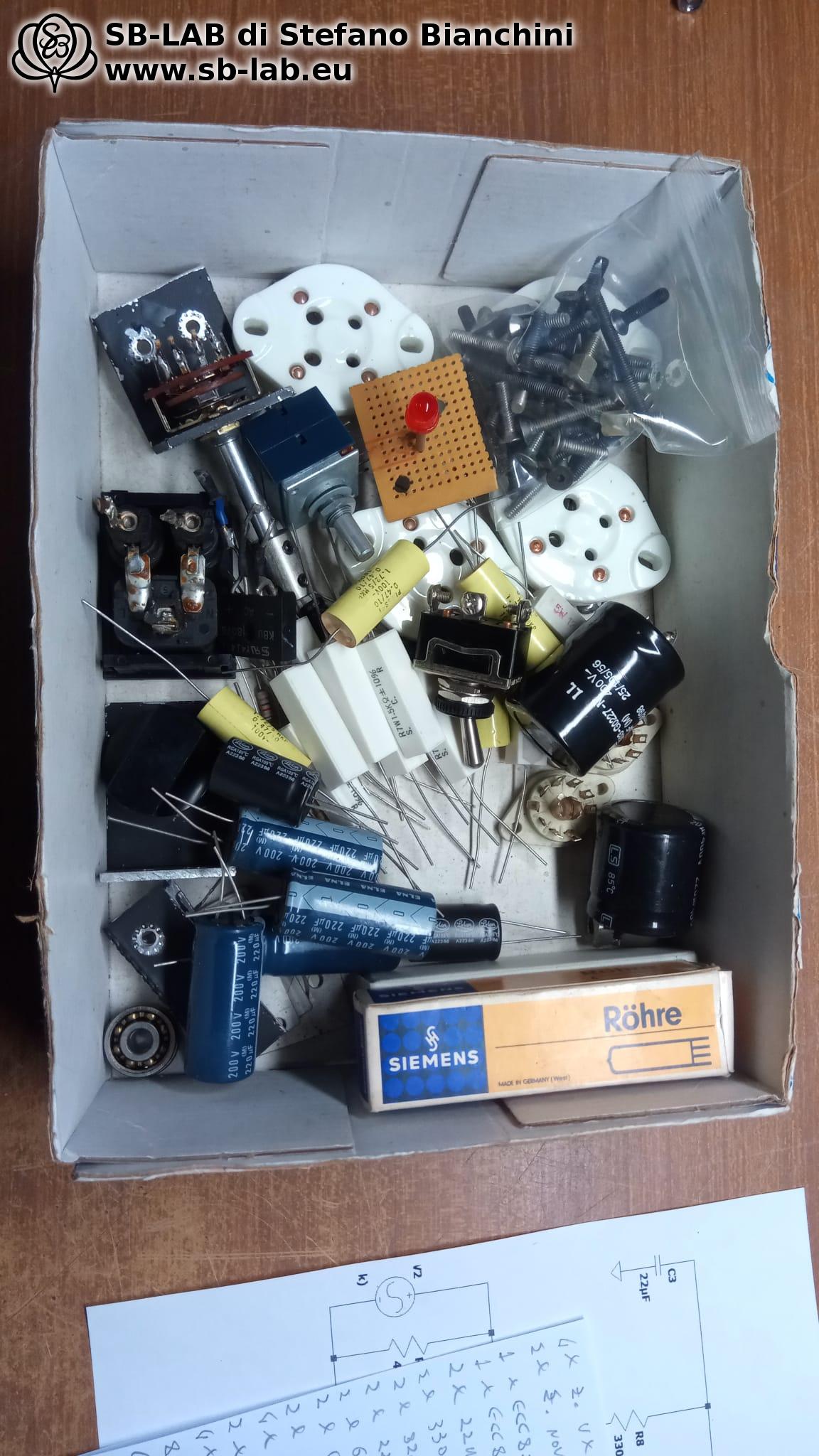
In the end, very little of the original amplifier remains: the chassis, with its characteristic transformer cans, the sockets, the RCA jacks, the banana posts for the speakers, a few power resistors, the IEC inlet, the LED indicator, the front knobs, and some small internal hardware. Everything else was removed, replaced, rethought from scratch.

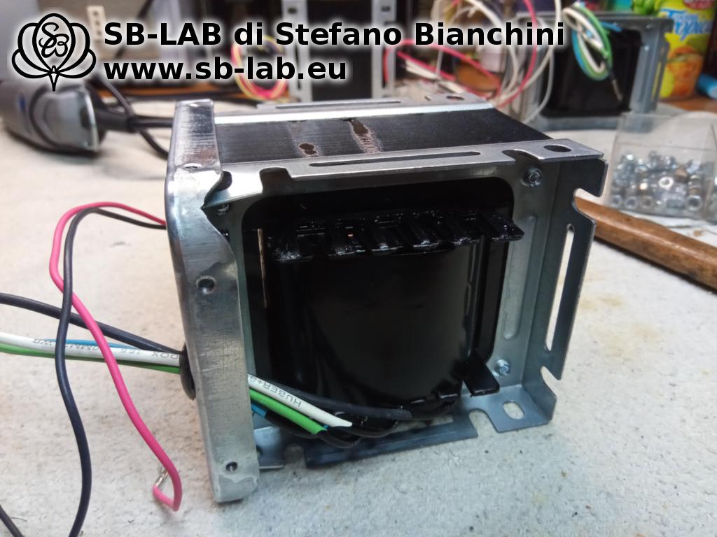
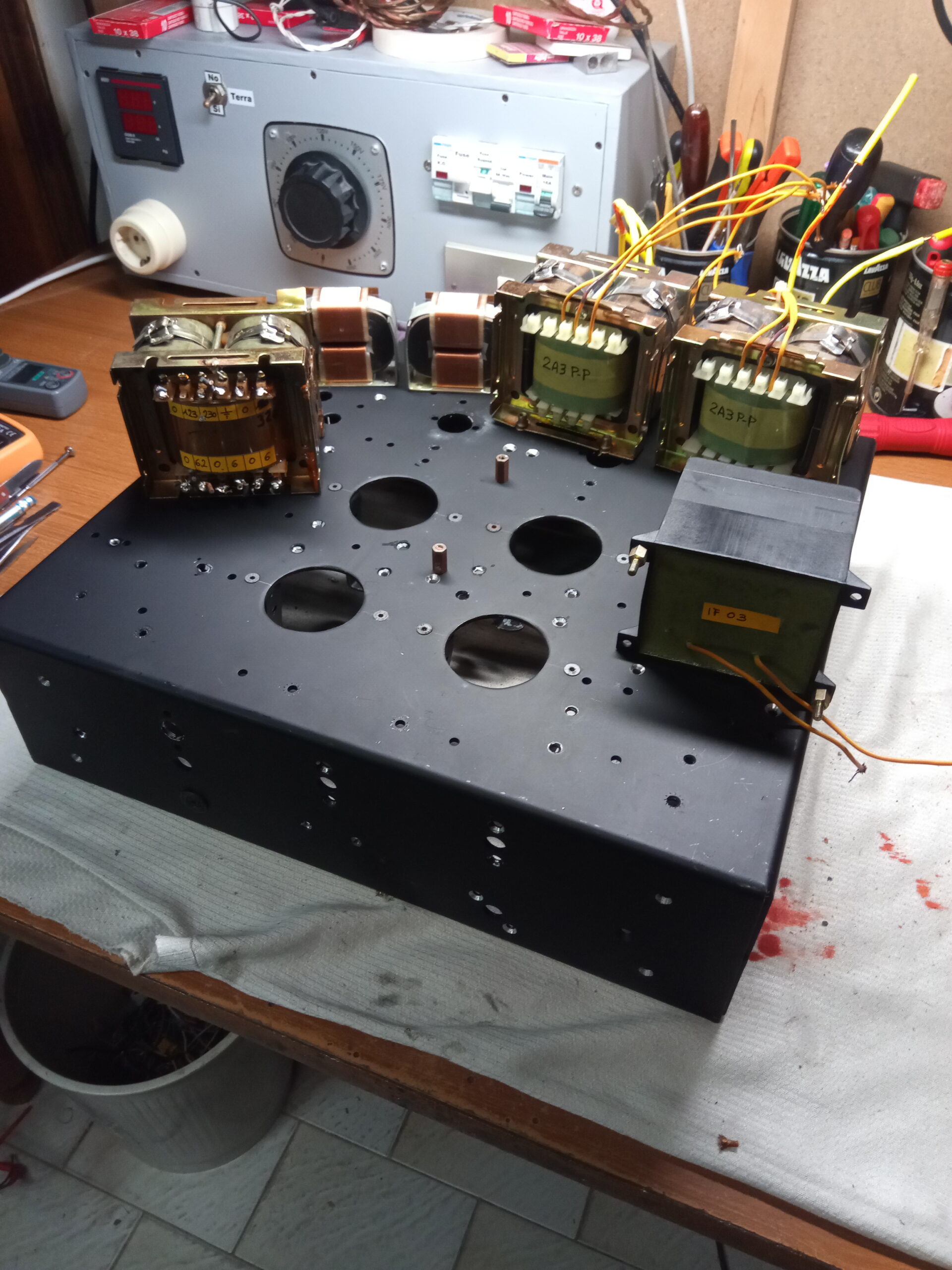
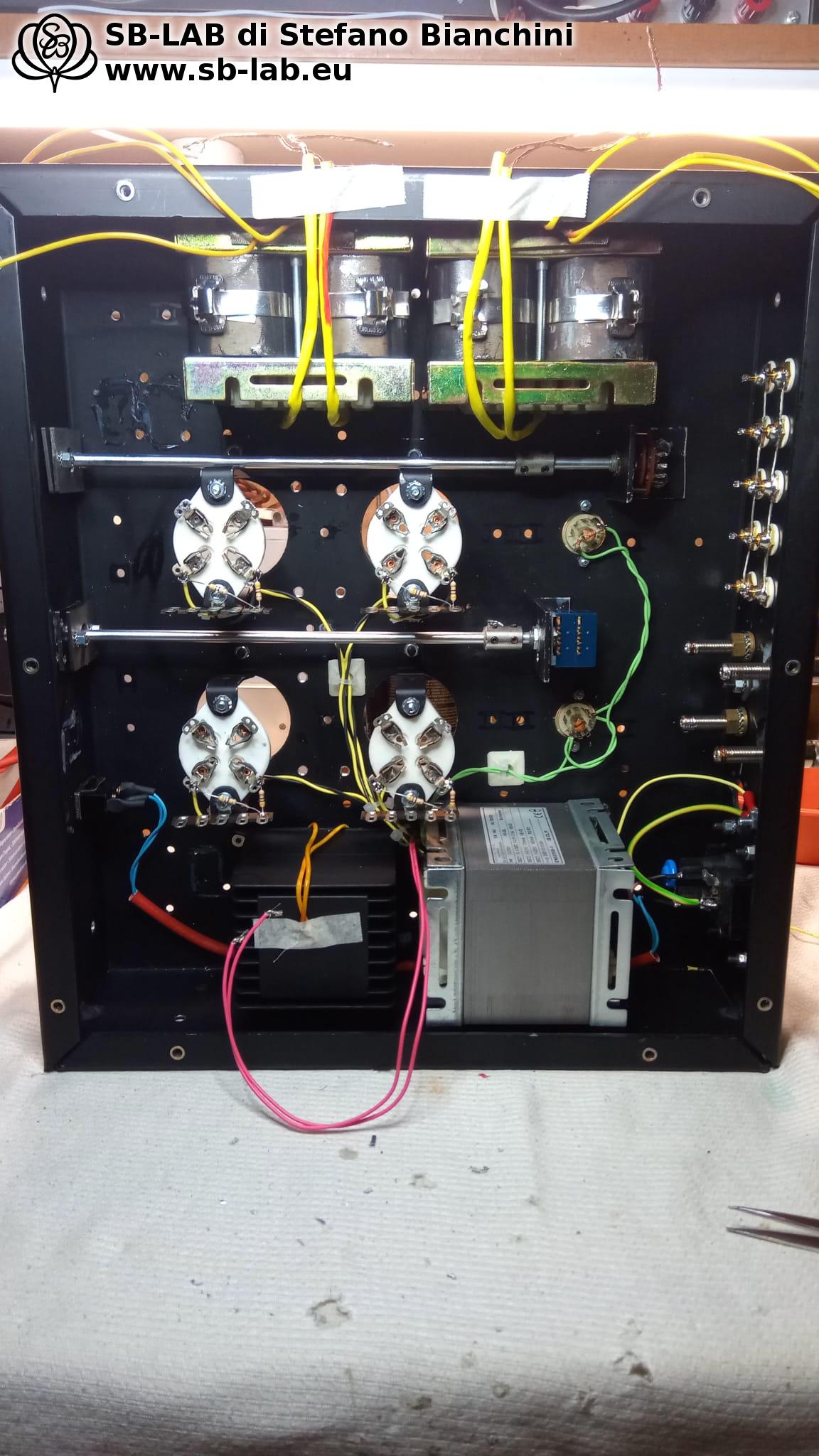
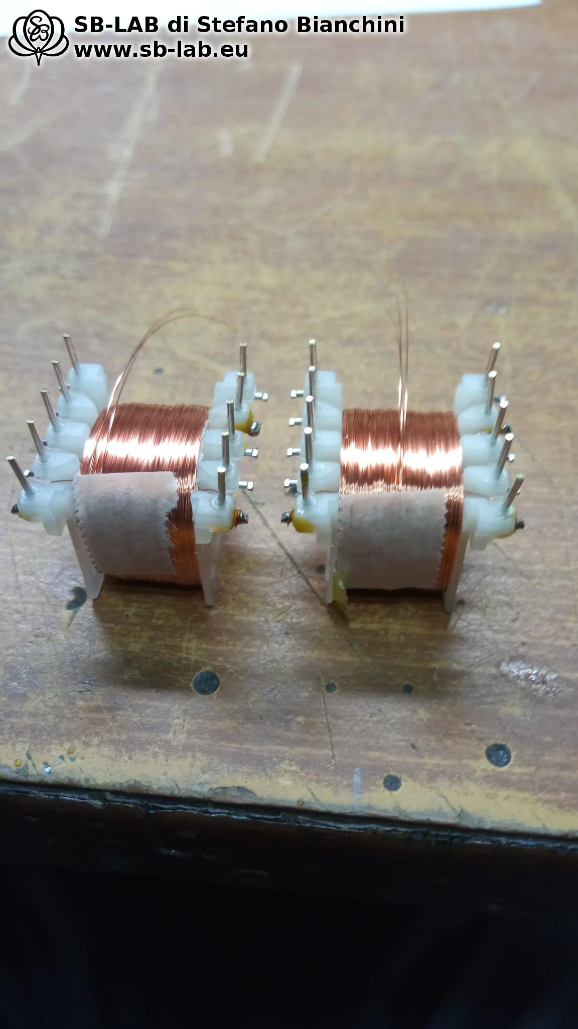
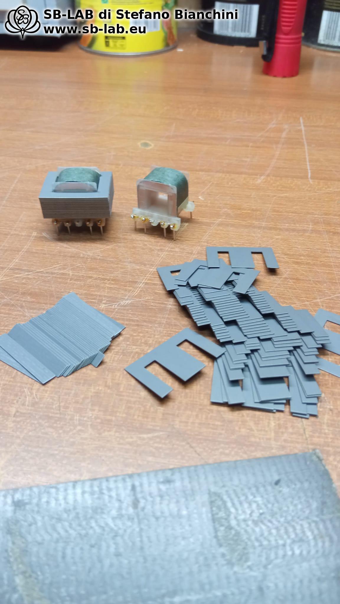
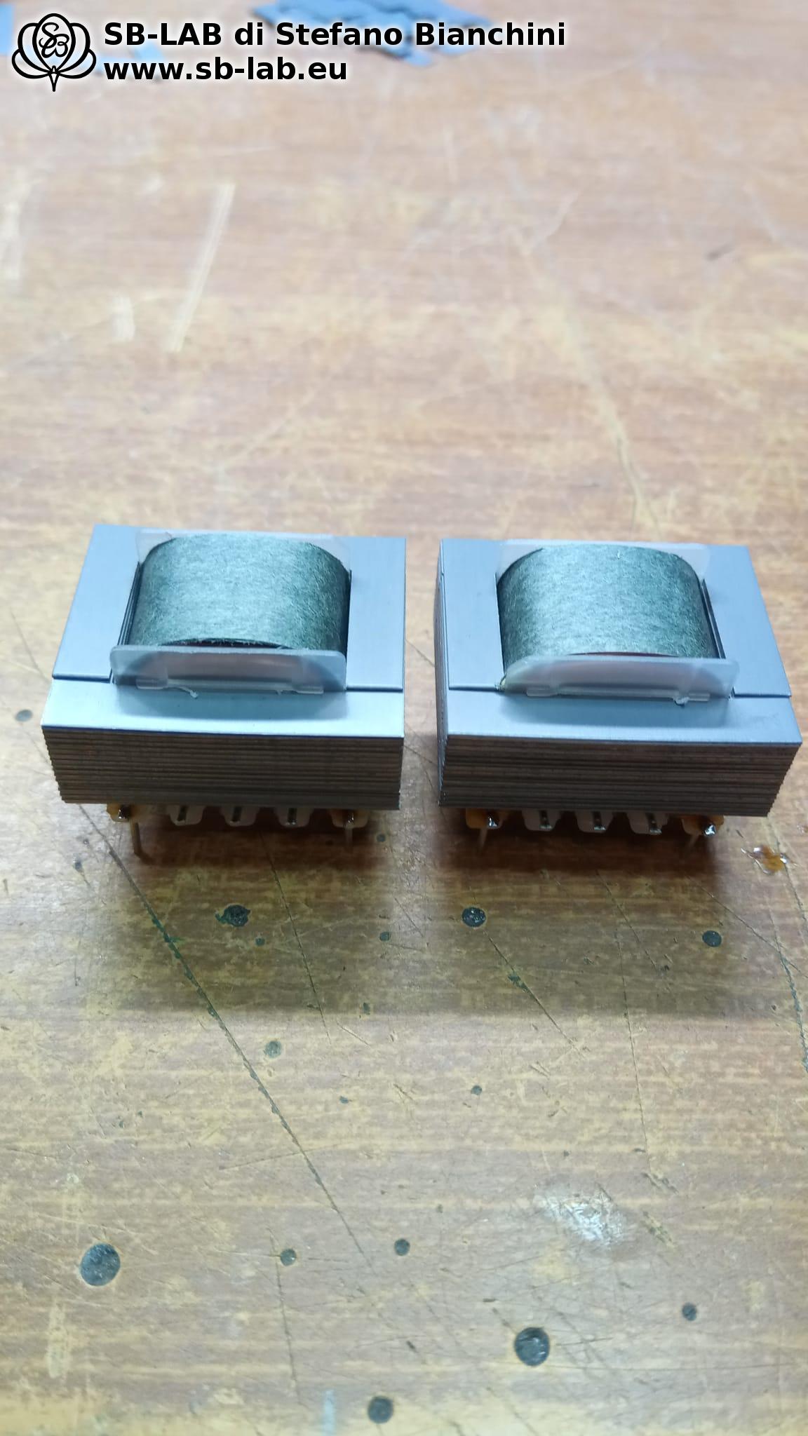
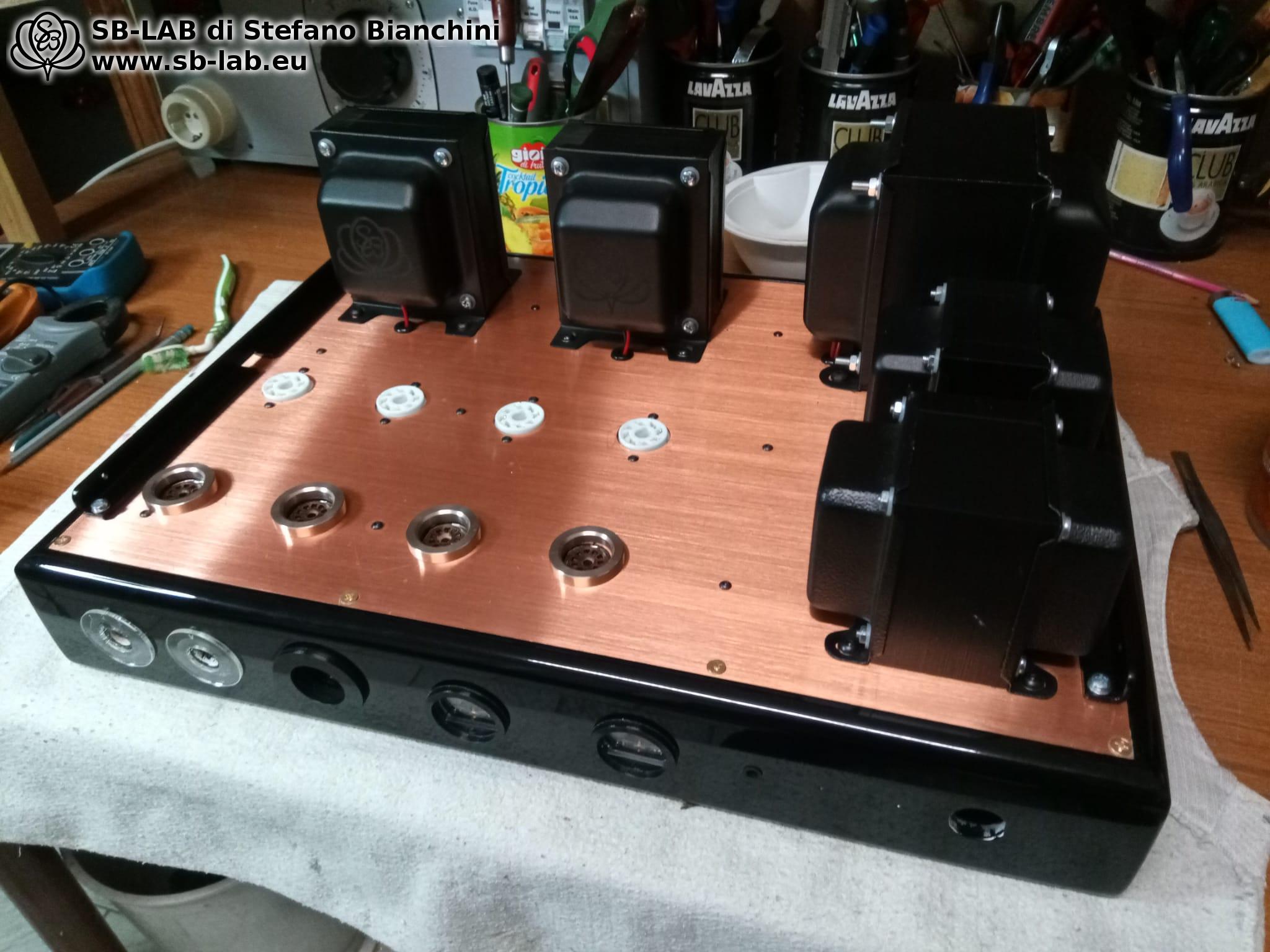
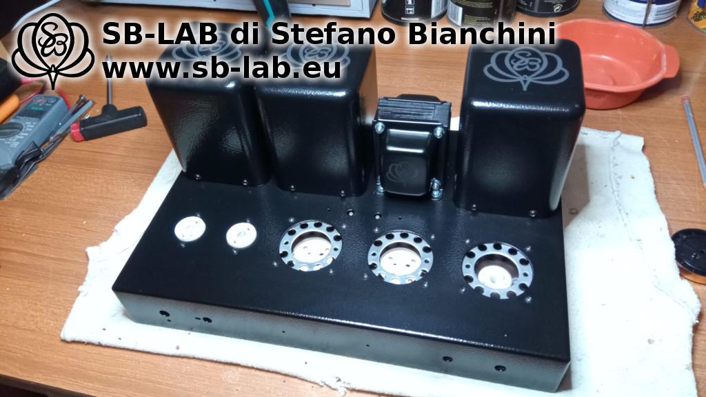
In the following photos you can see the two SE2K5-2A3 output transformers, designed expressly for use with 2A3 tubes in single-ended configuration, and the 23S48 power transformer, sized to ensure stability and a silent background. For this build they were made with mounting frames instead of the usual covers — a functional choice necessary to house them inside the original sheet-metal boxes of the Chinese chassis without giving up robustness and shielding.
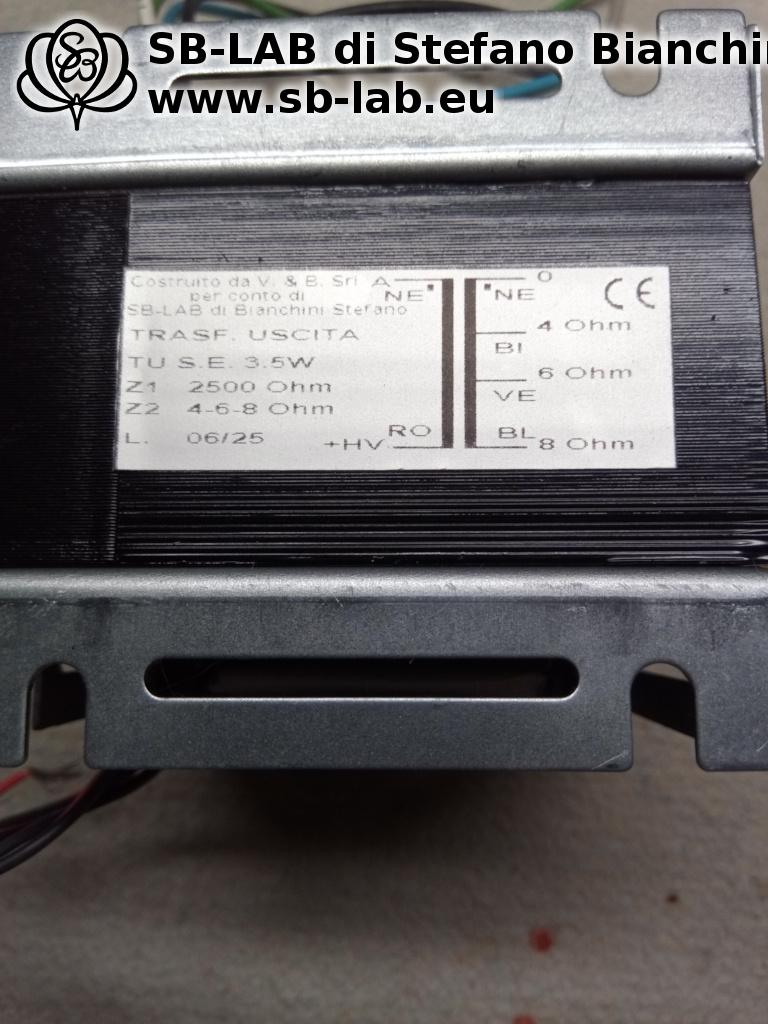
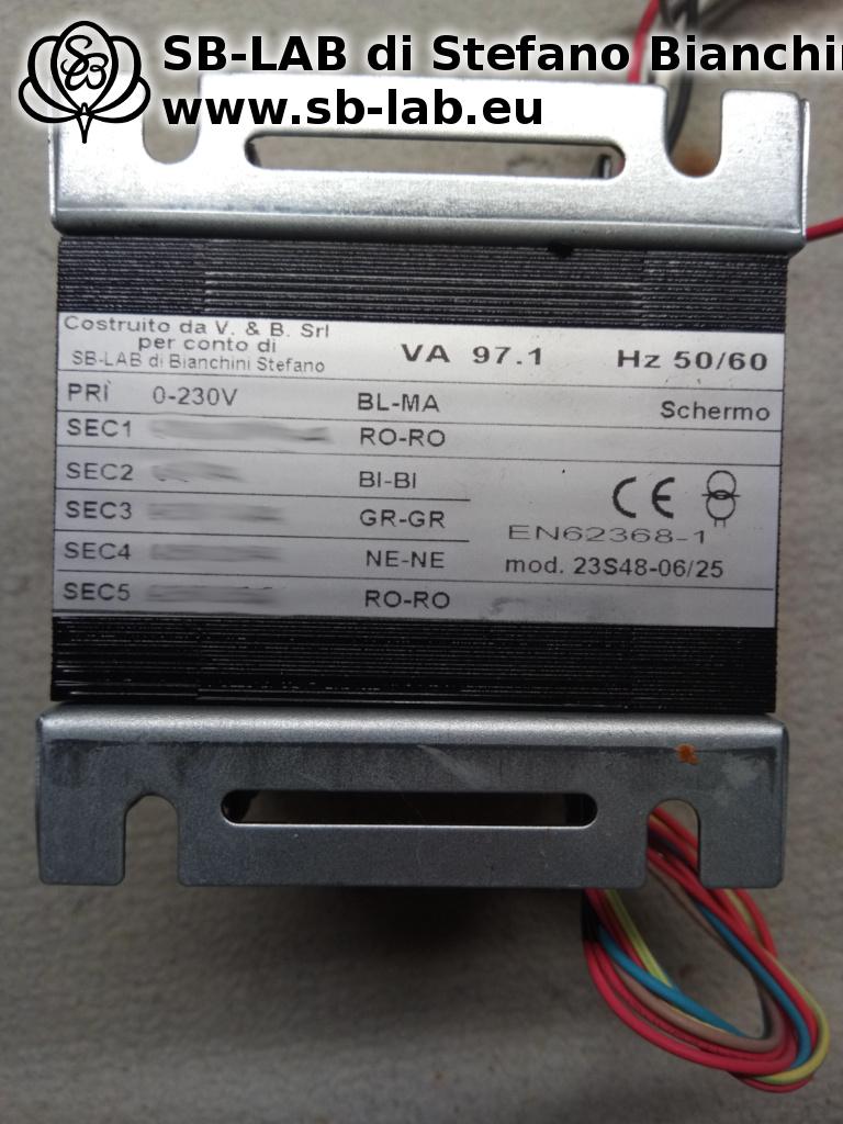
Alongside them, the 18S5200 choke, an integral part of the inductive power supply group that ensures clean, deep filtering. The entire transformer set — SE2K5-2A3, 23S48, and 18S5200 together with the complete schematic — is available as a premium schematic, for those who want to replicate a similar project starting from components selected and designed specifically for this topology.

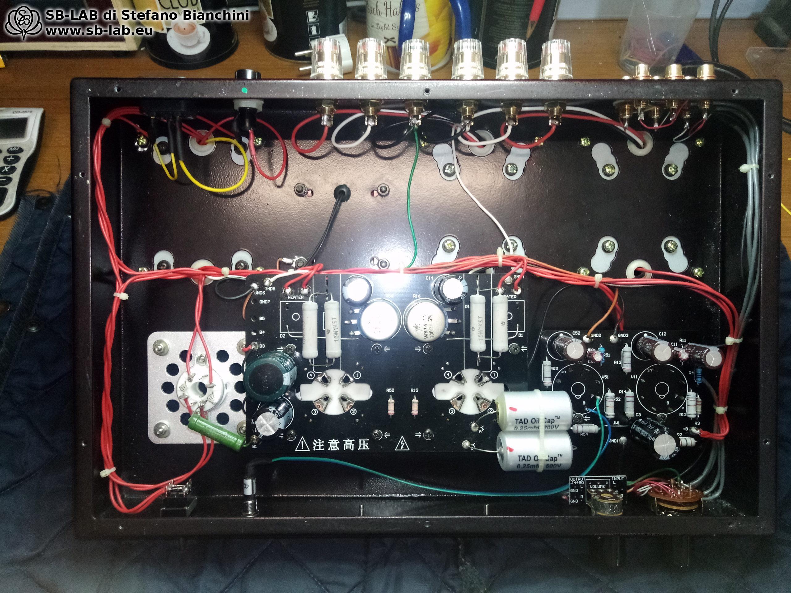
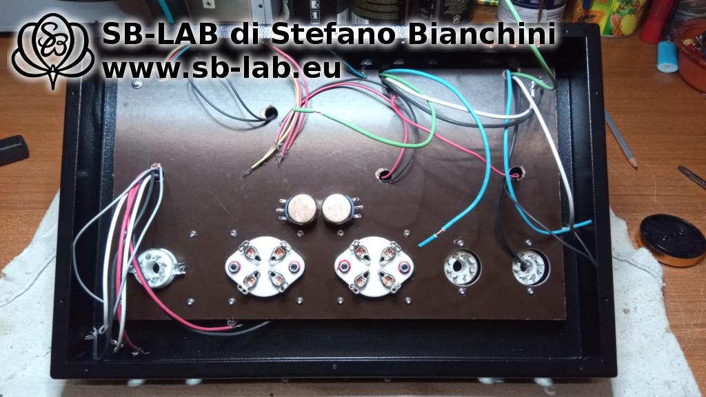
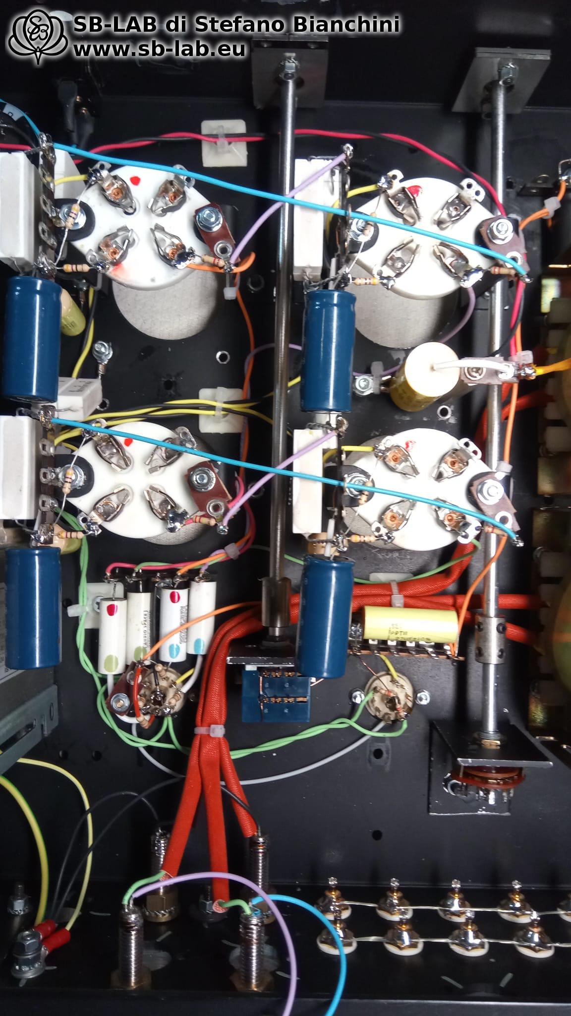
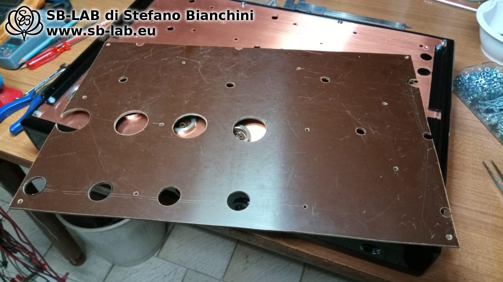
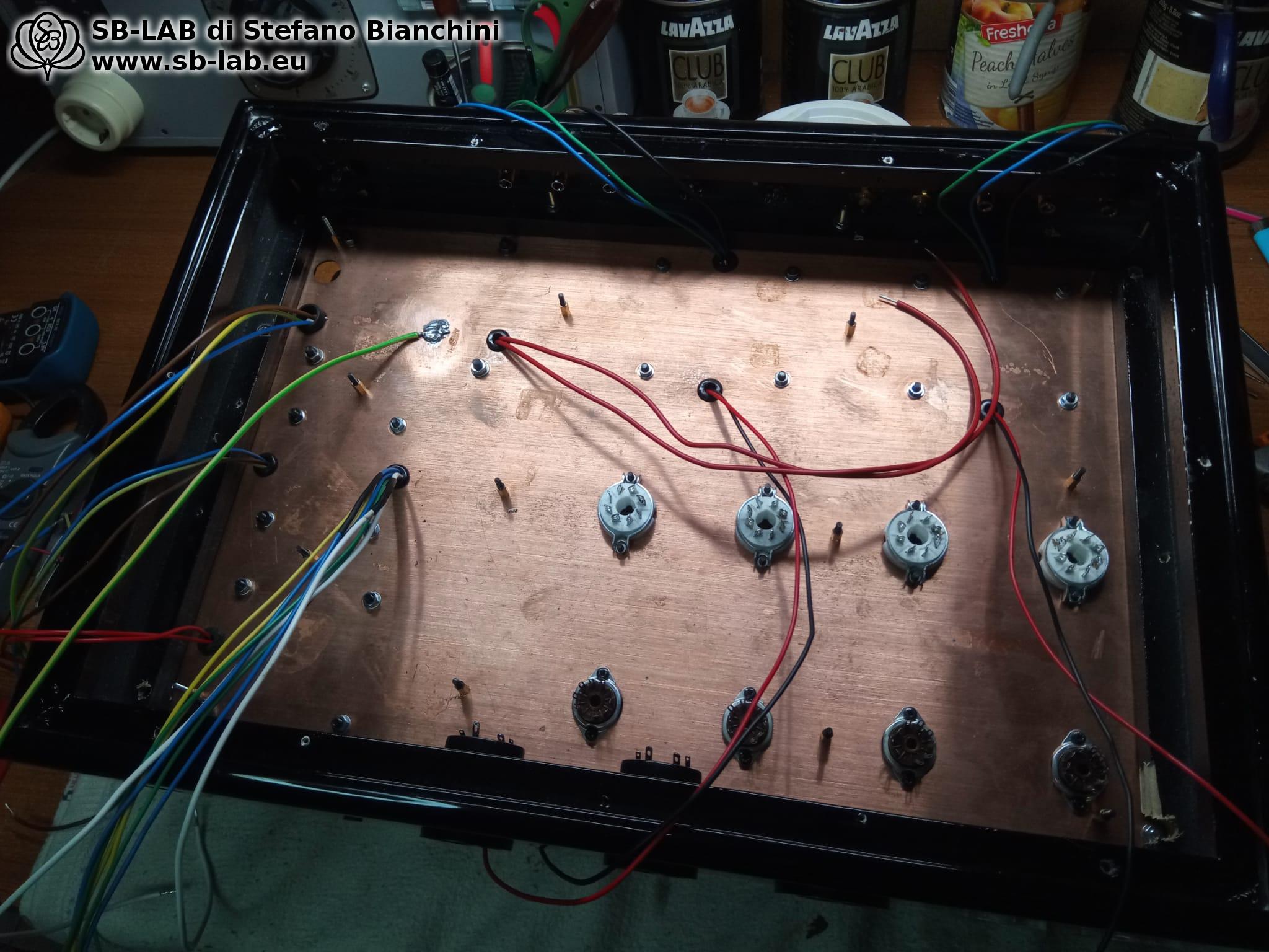
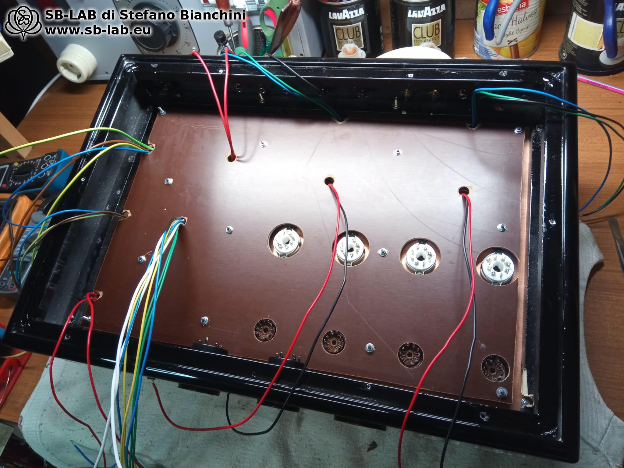
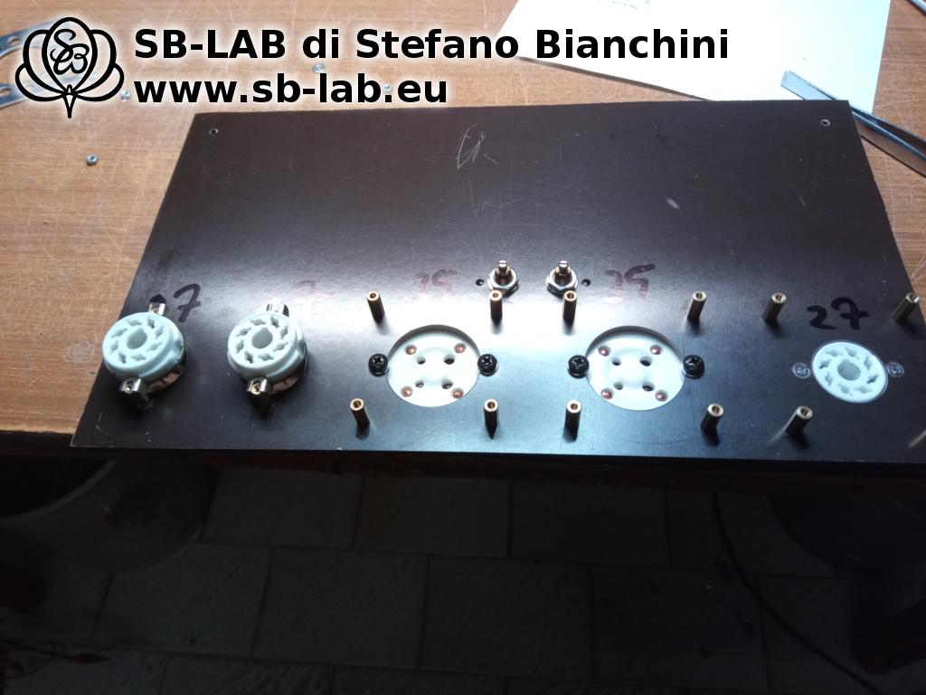
In the next step, I created and installed a bakelite board on which all the sockets were mounted, ready to receive the point-to-point wiring. A neat, robust, and easily serviceable solution. The board was assembled together with the transformers and the chassis, marking the point of no return: from that moment on, Nyx Aeterna was taking concrete shape.
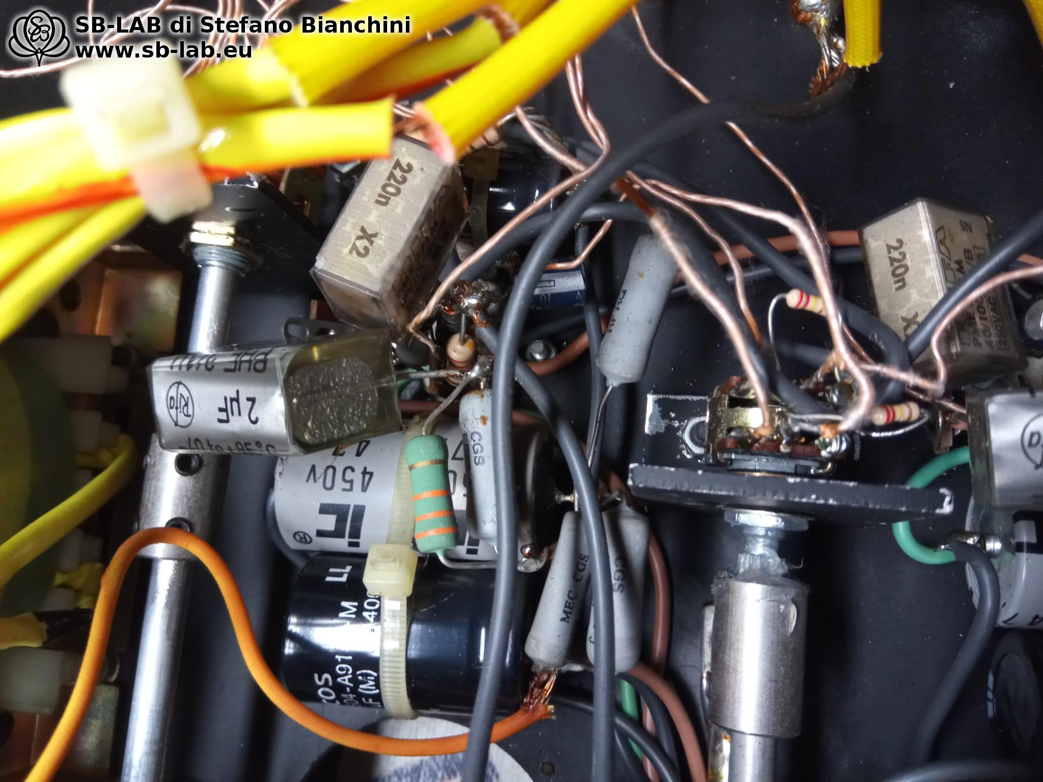
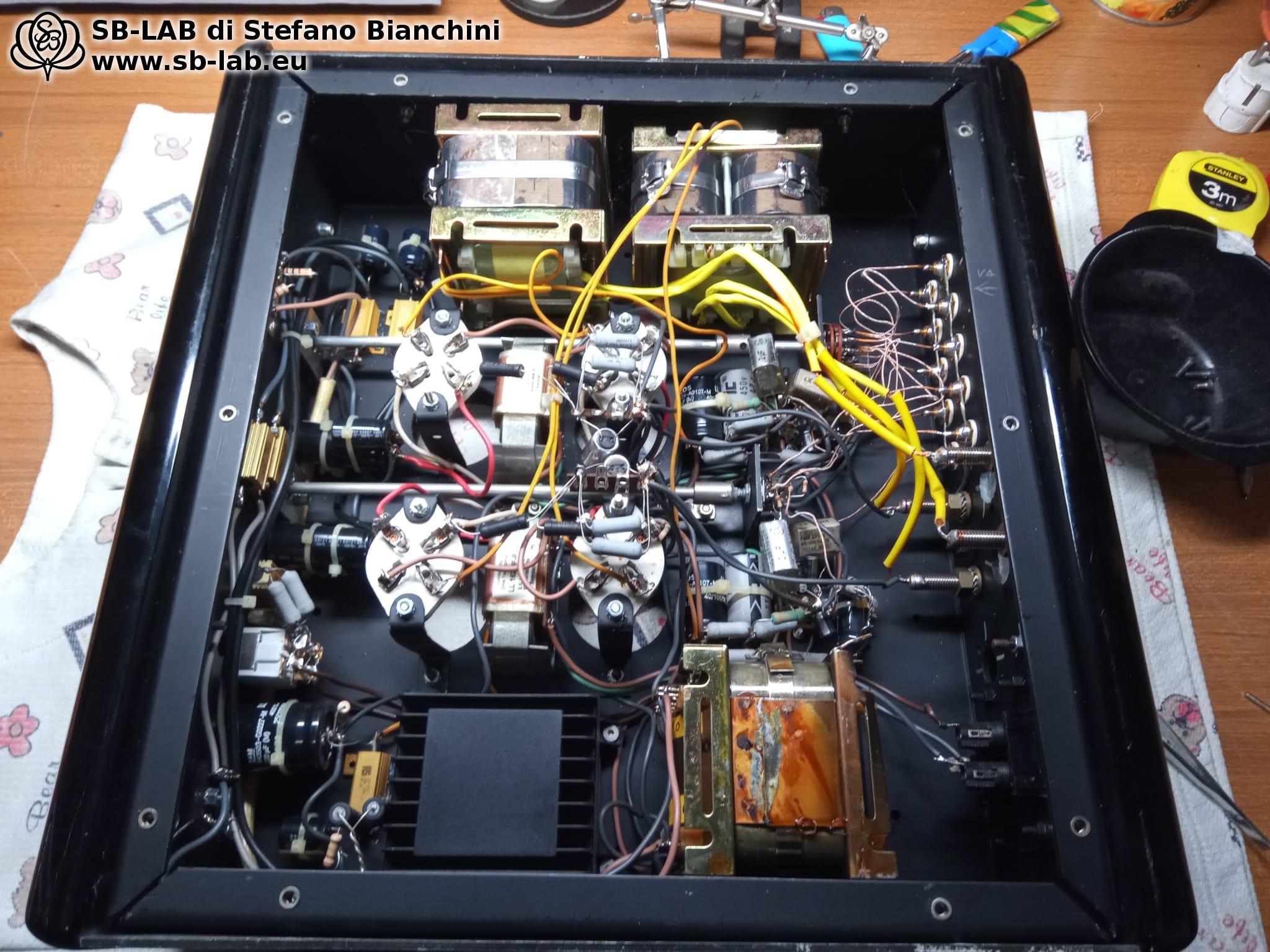
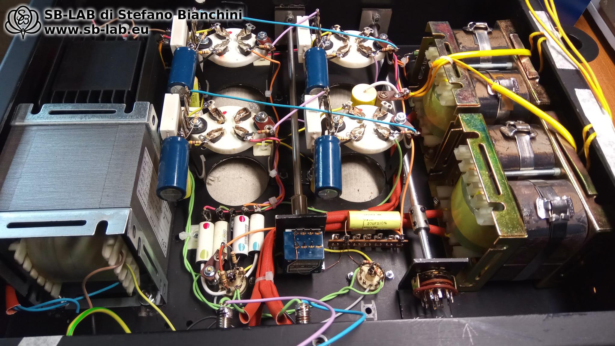
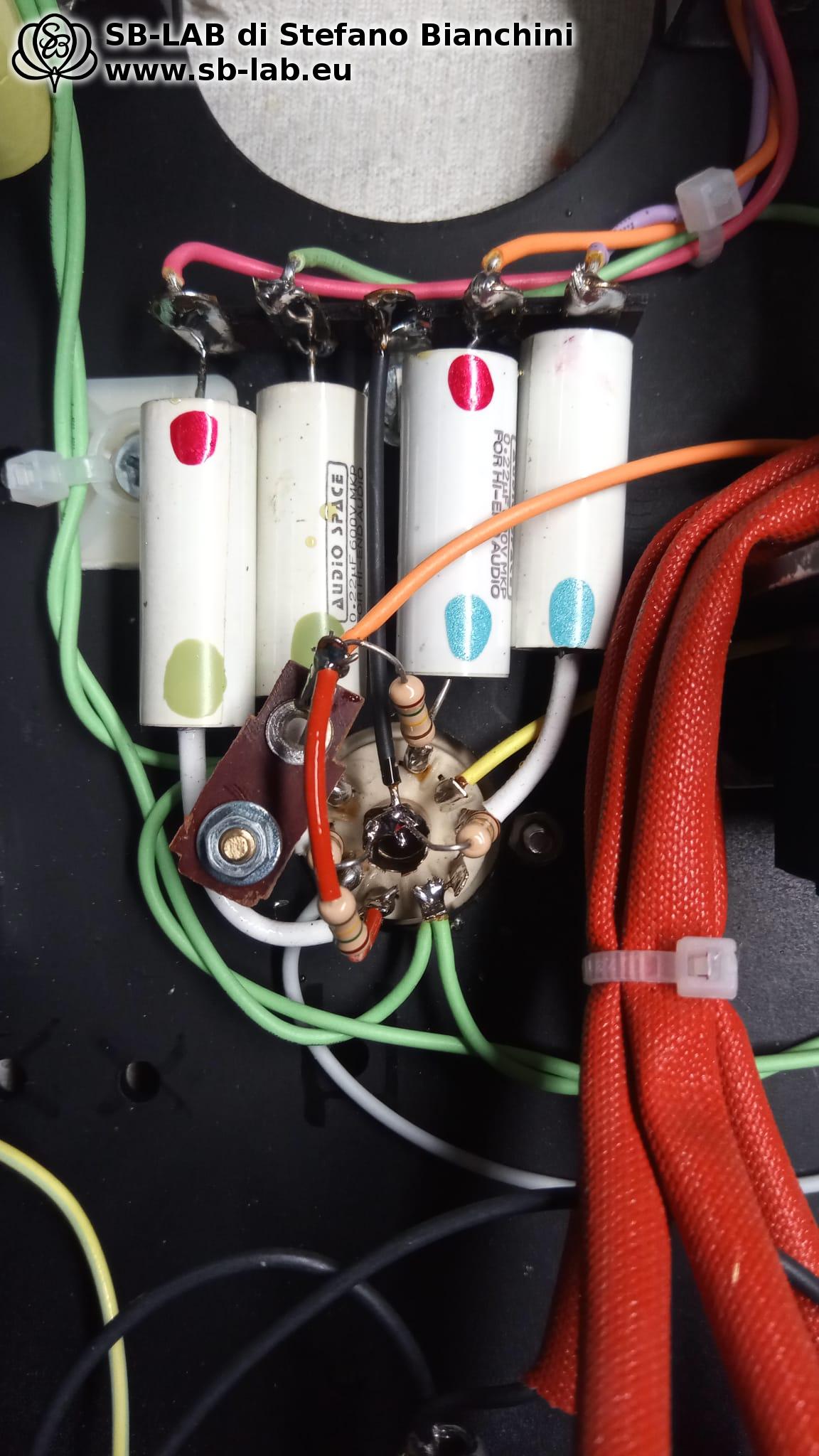
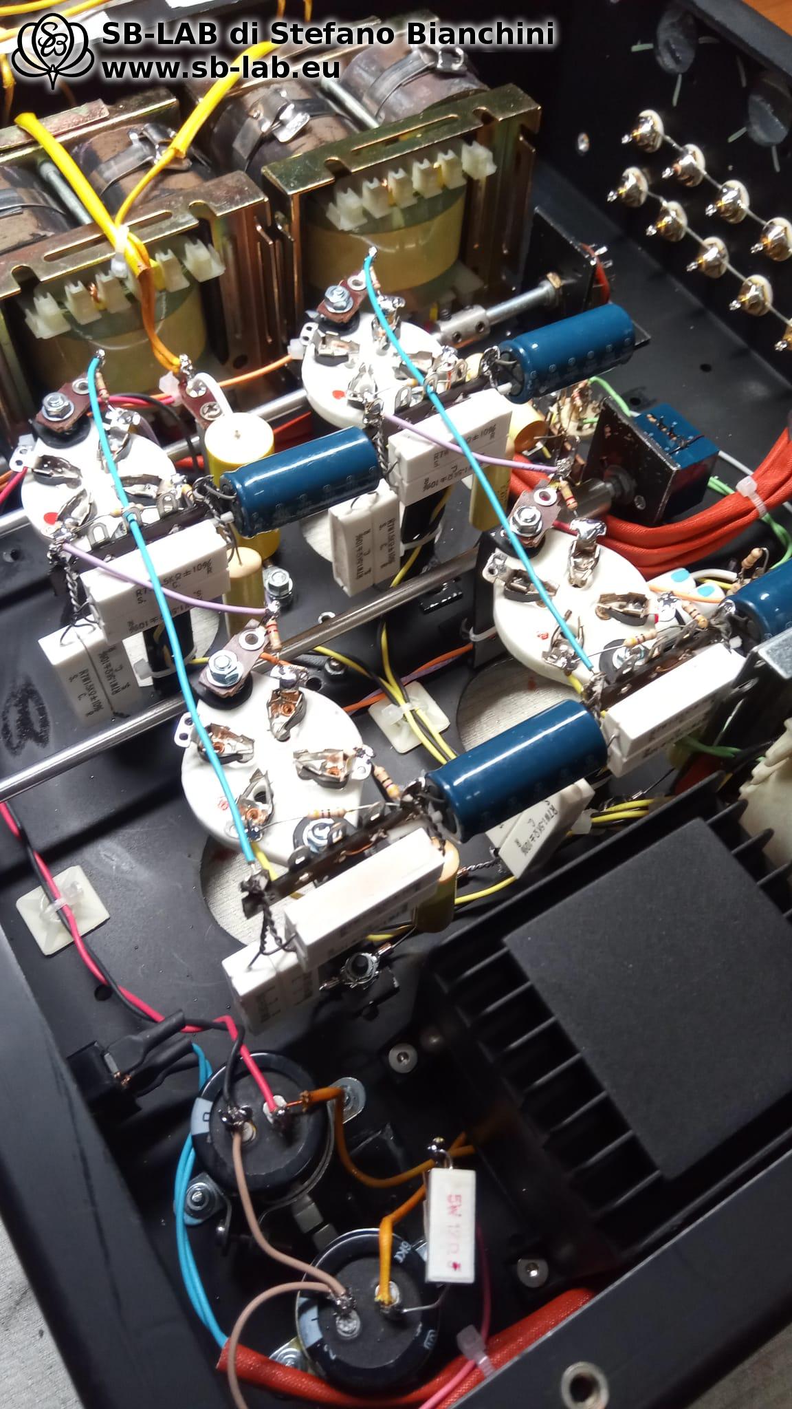
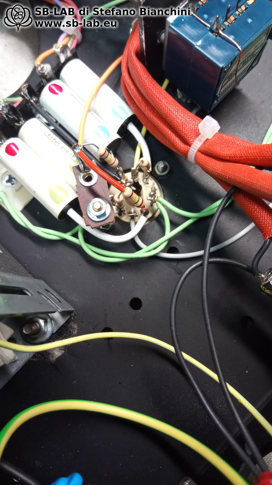
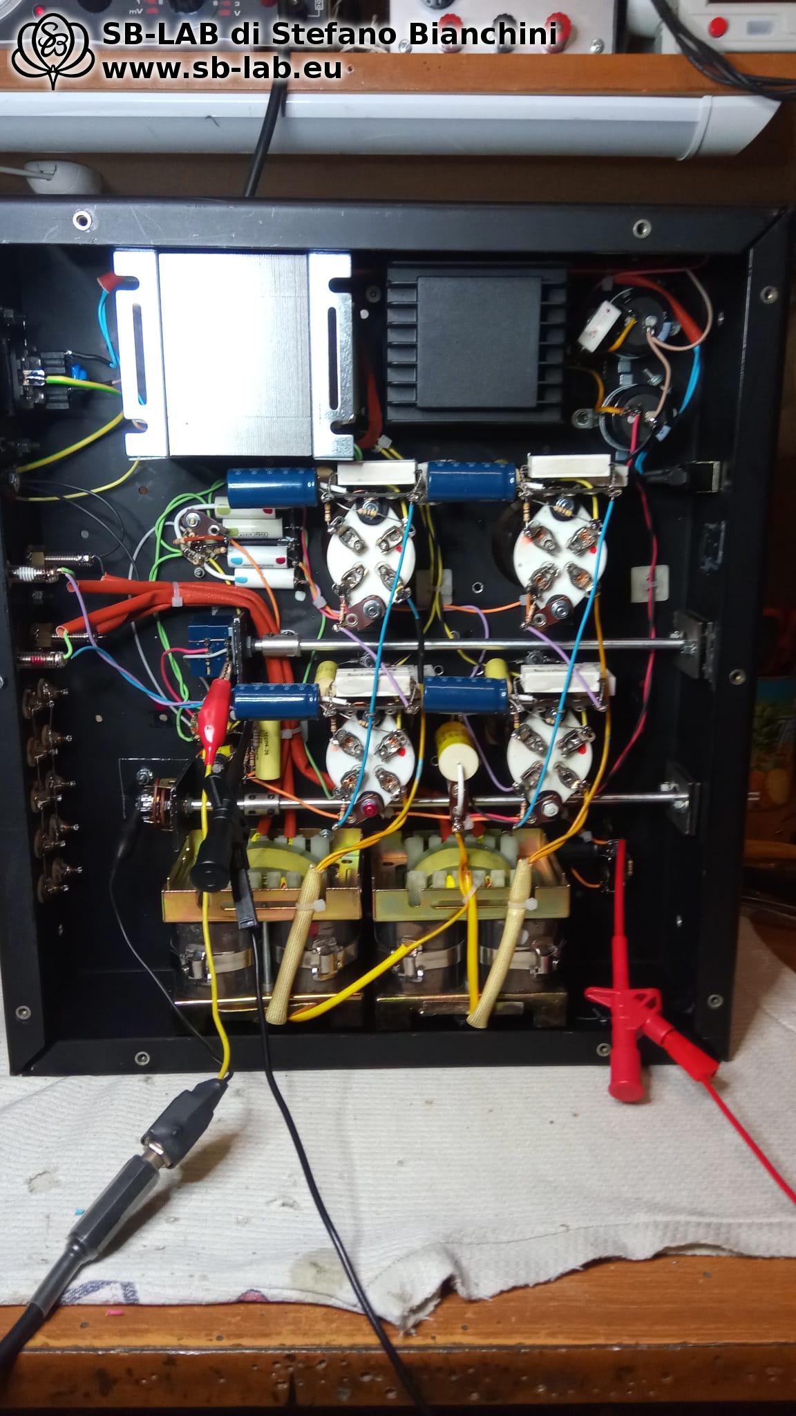
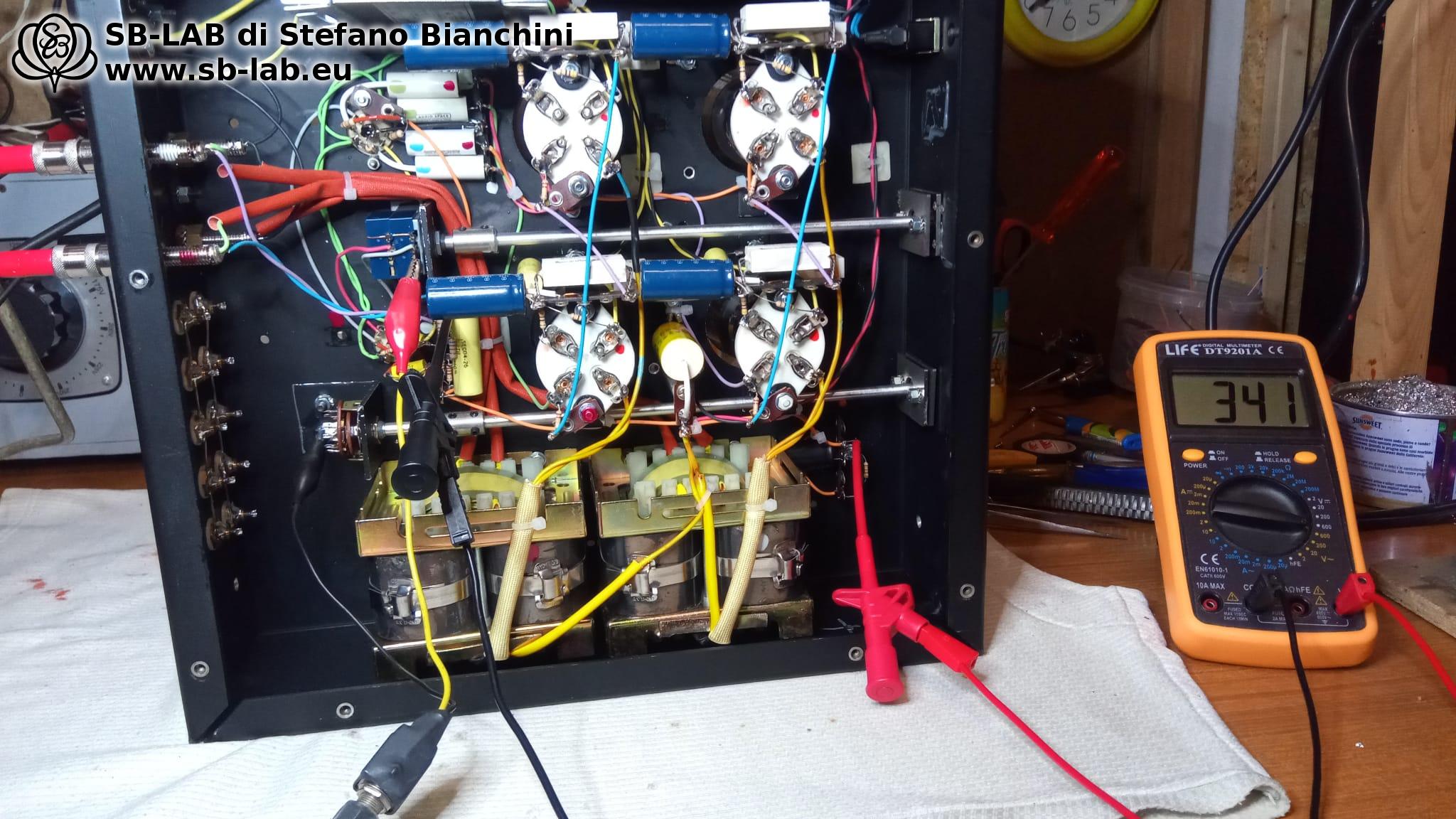
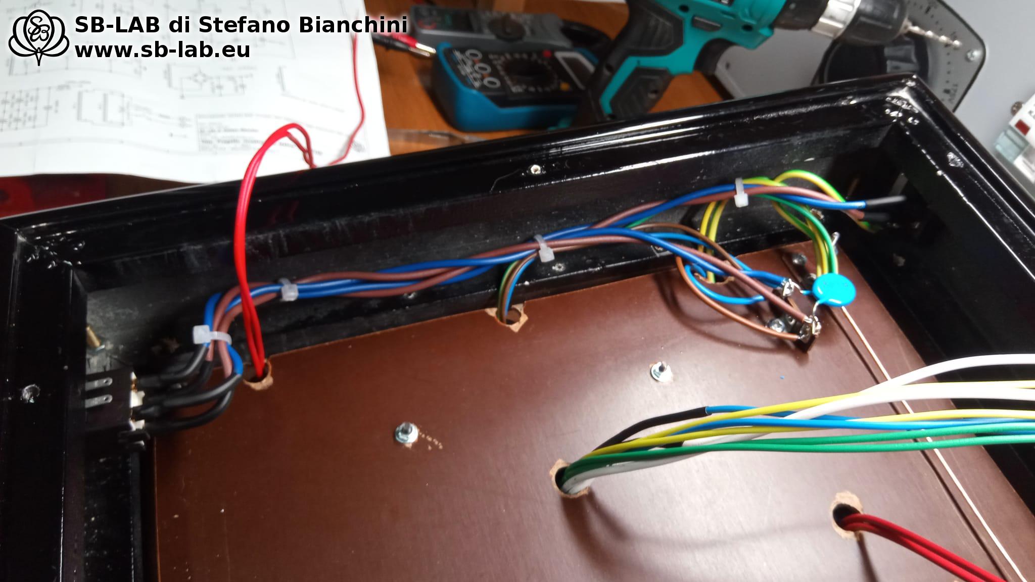
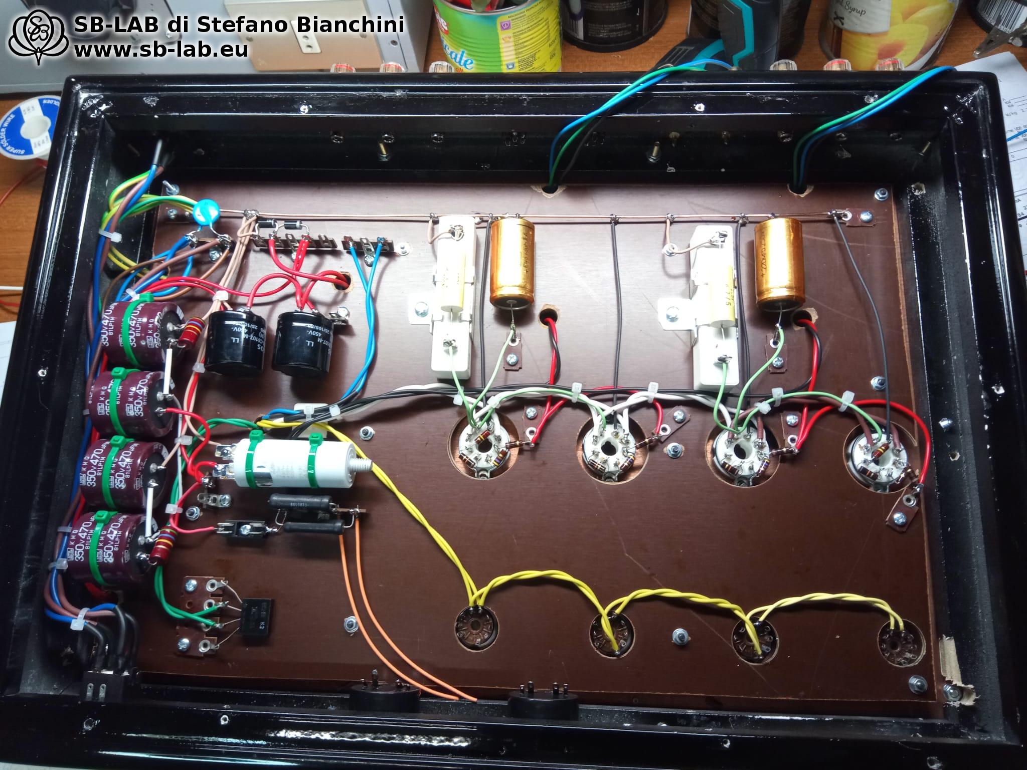
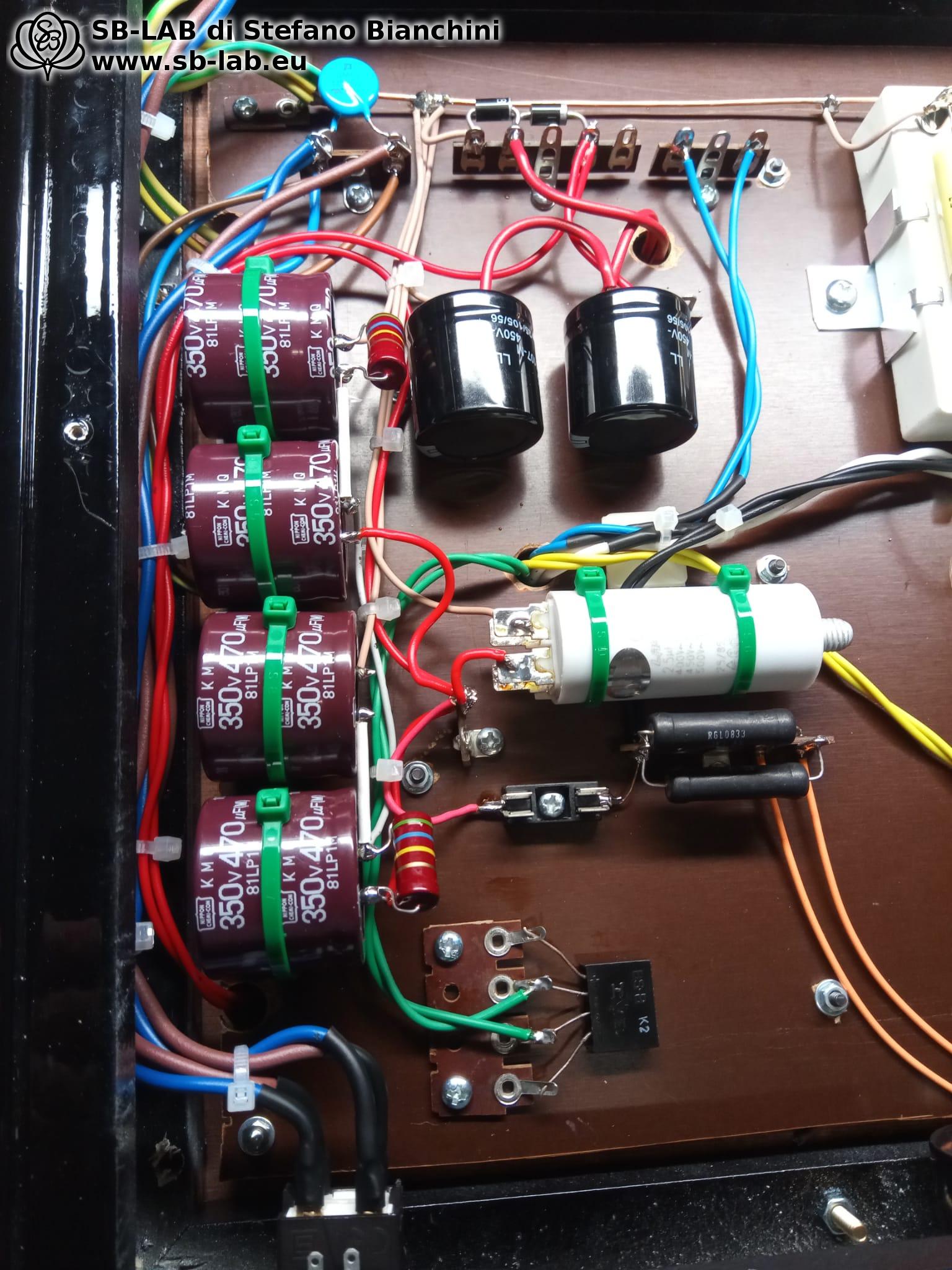
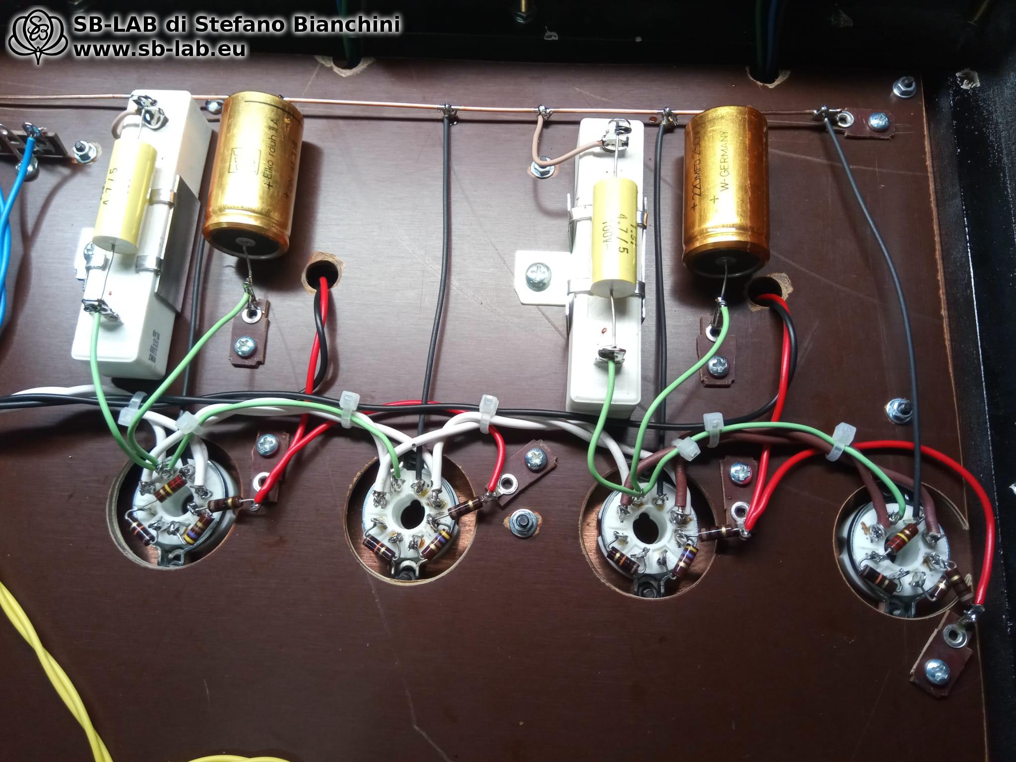
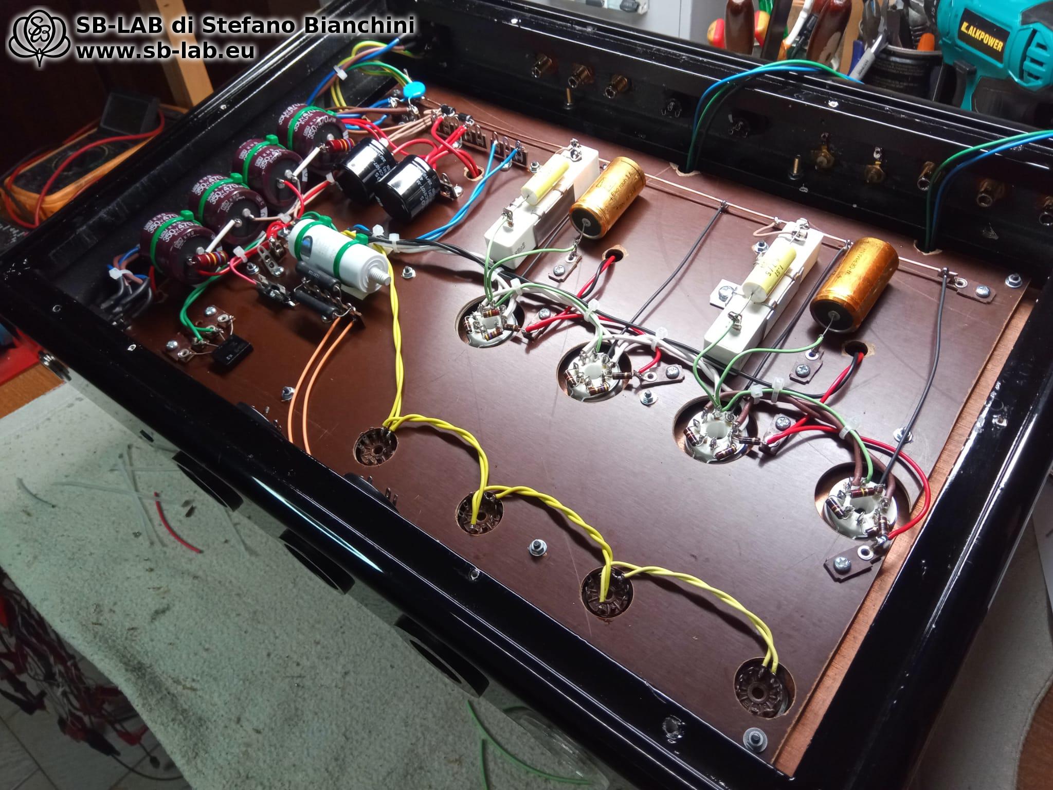
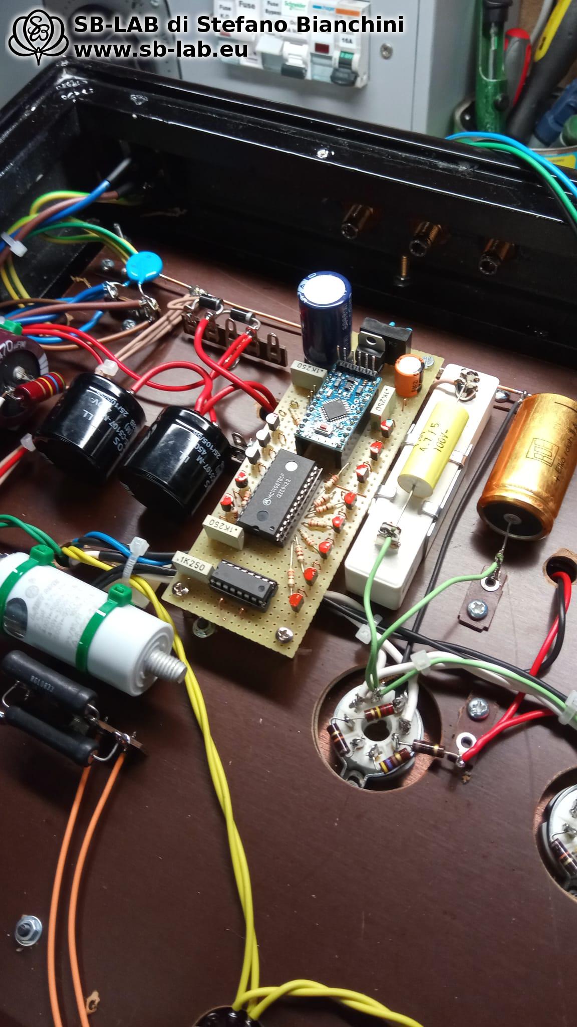
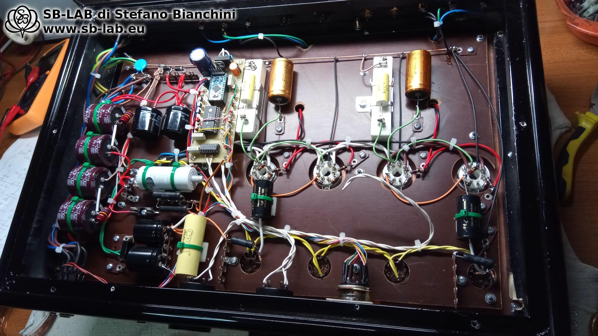
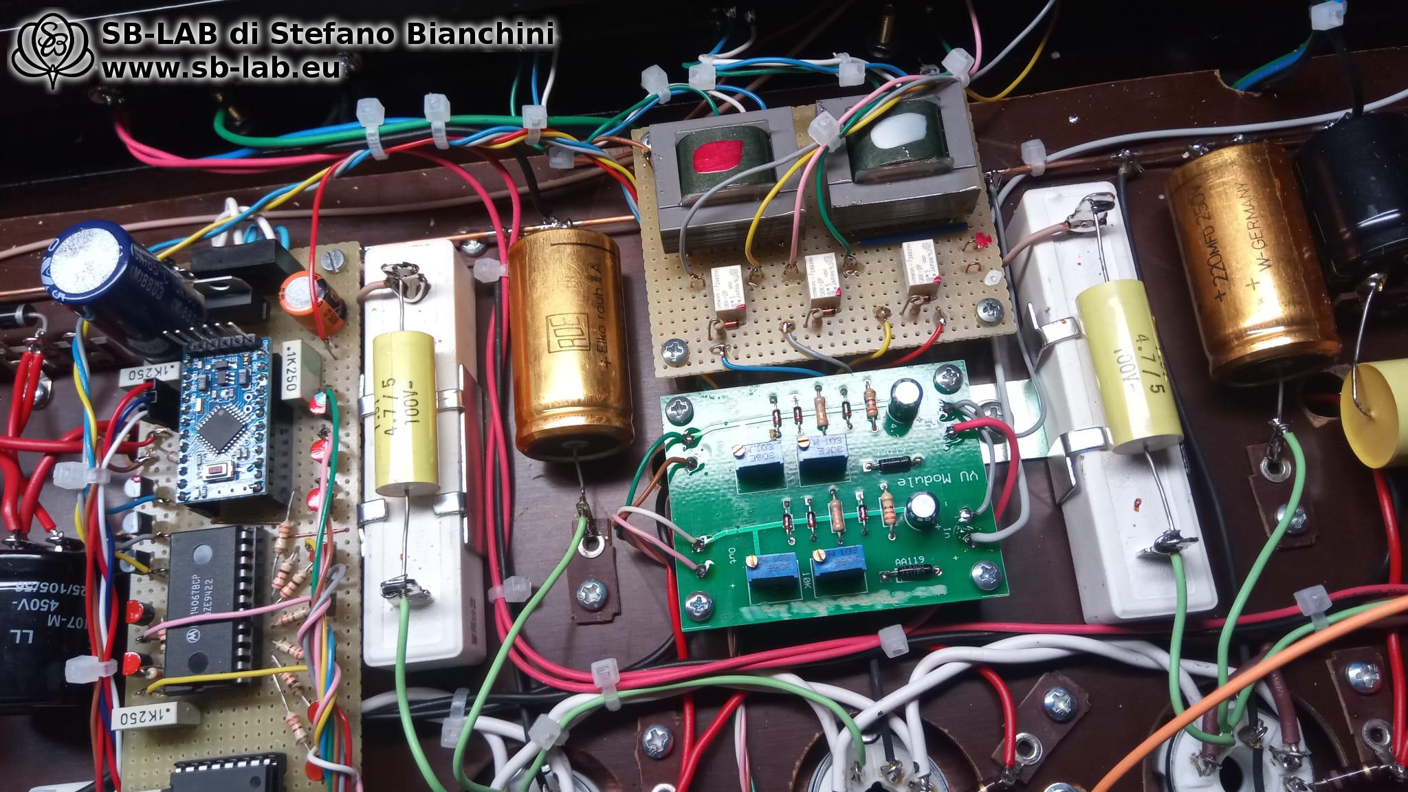
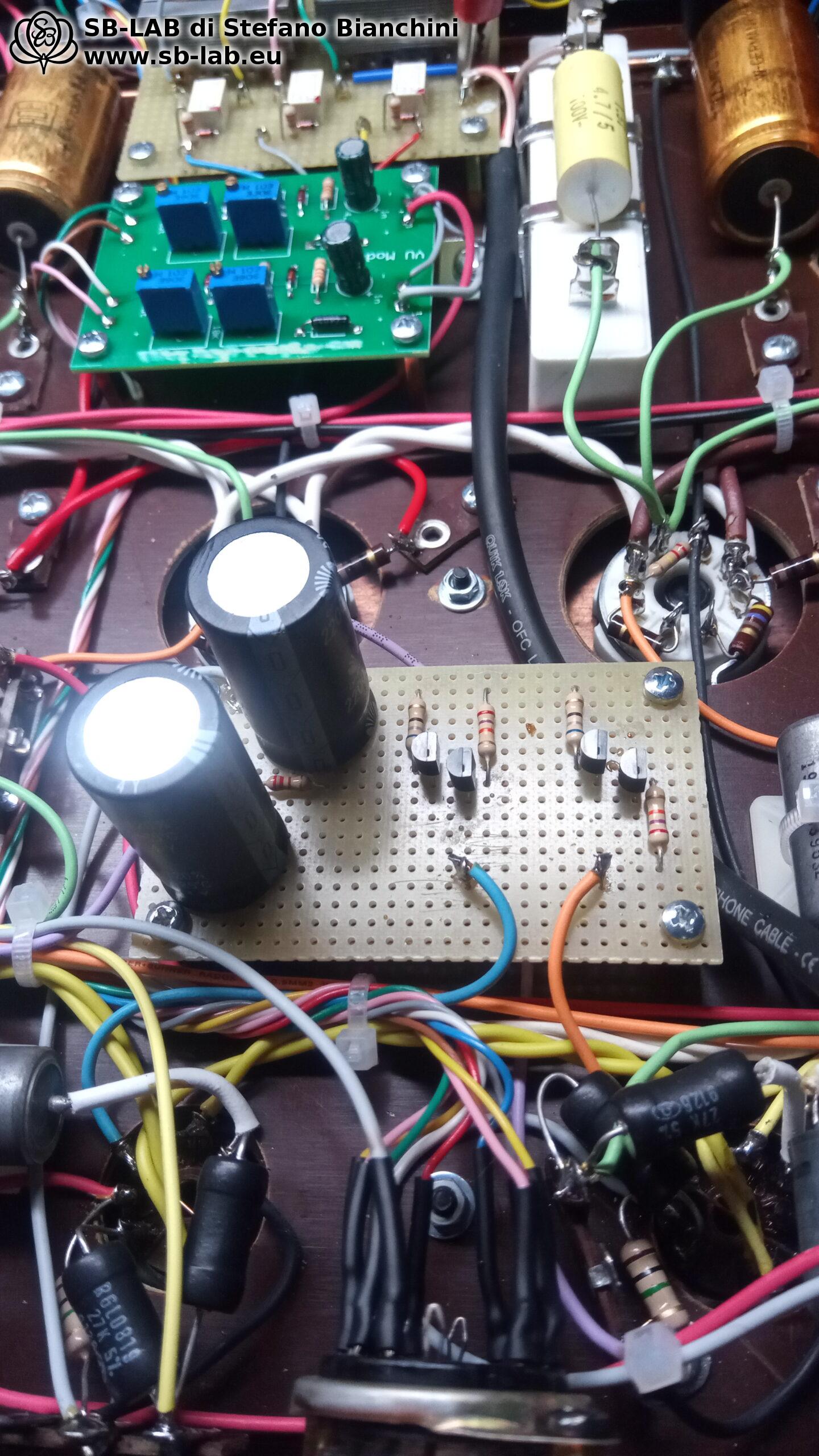
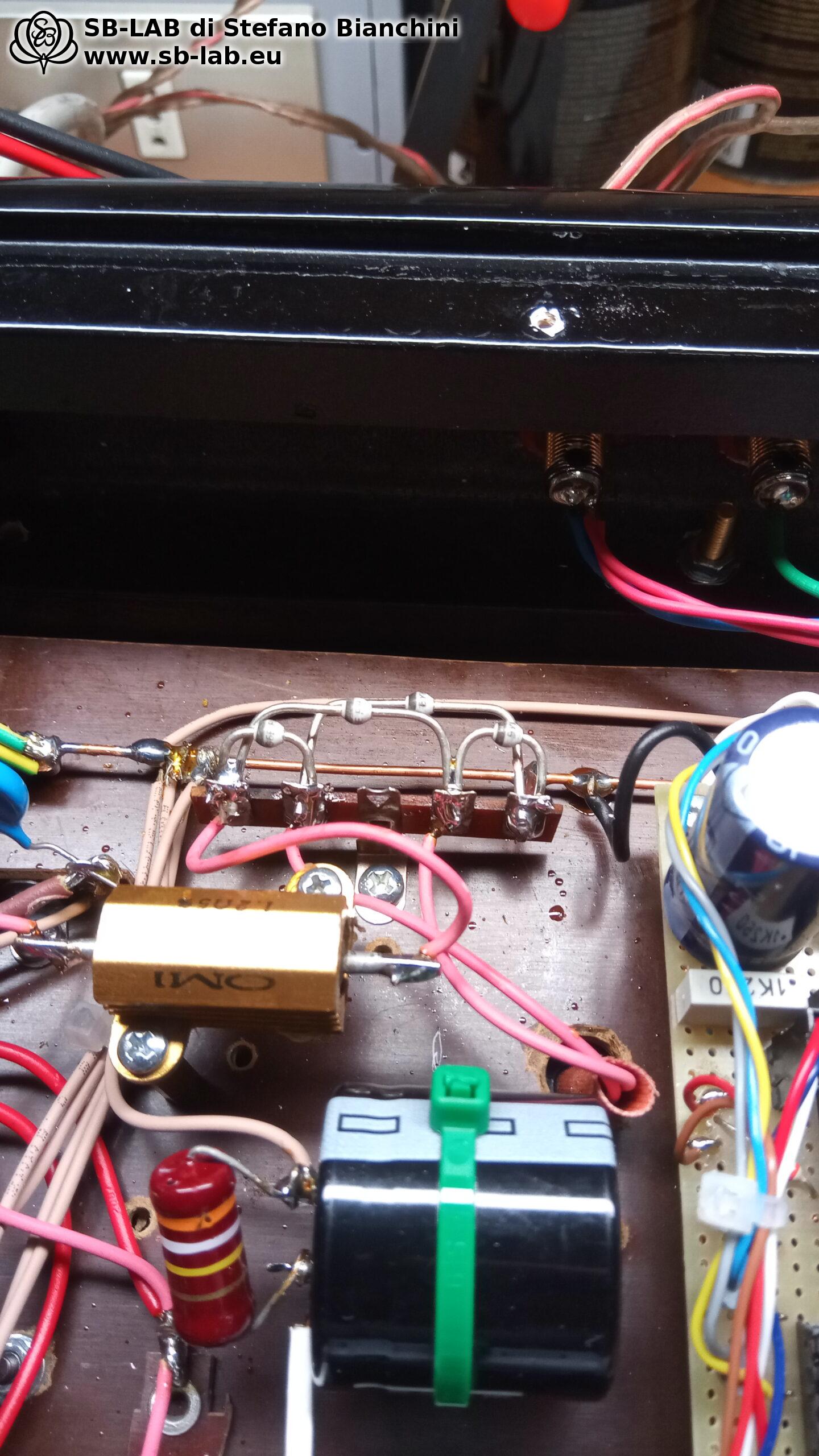
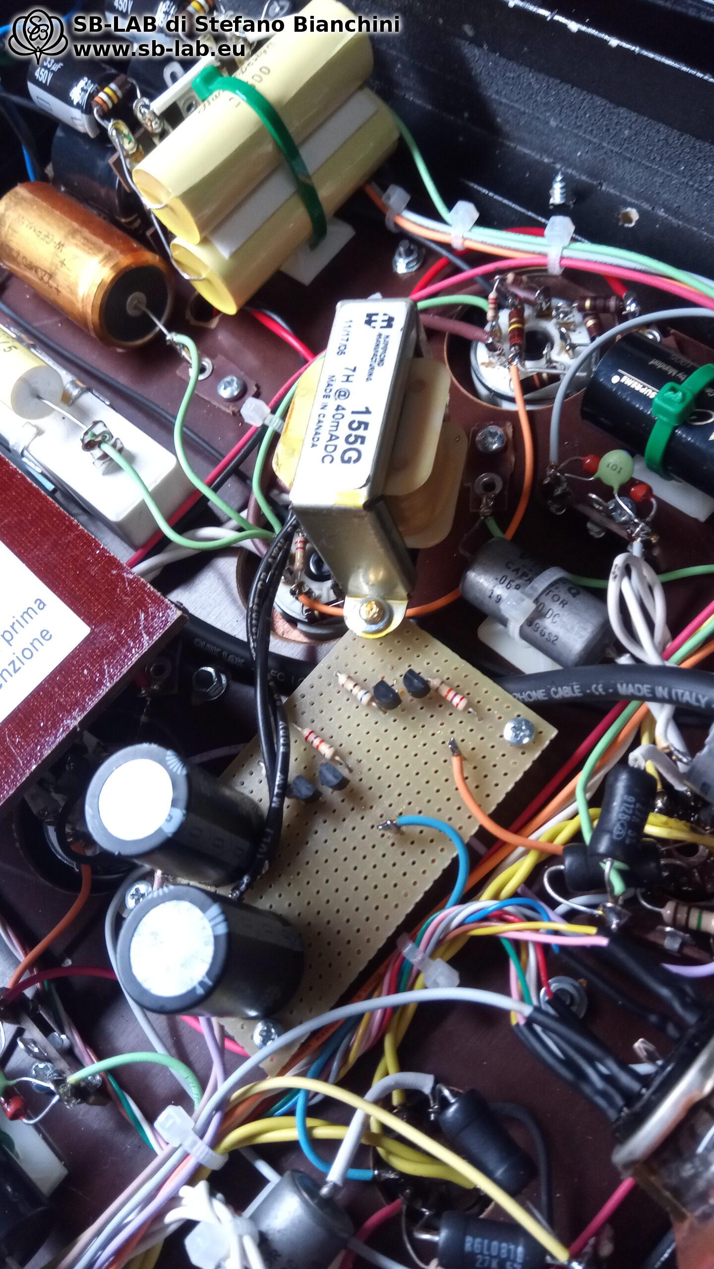
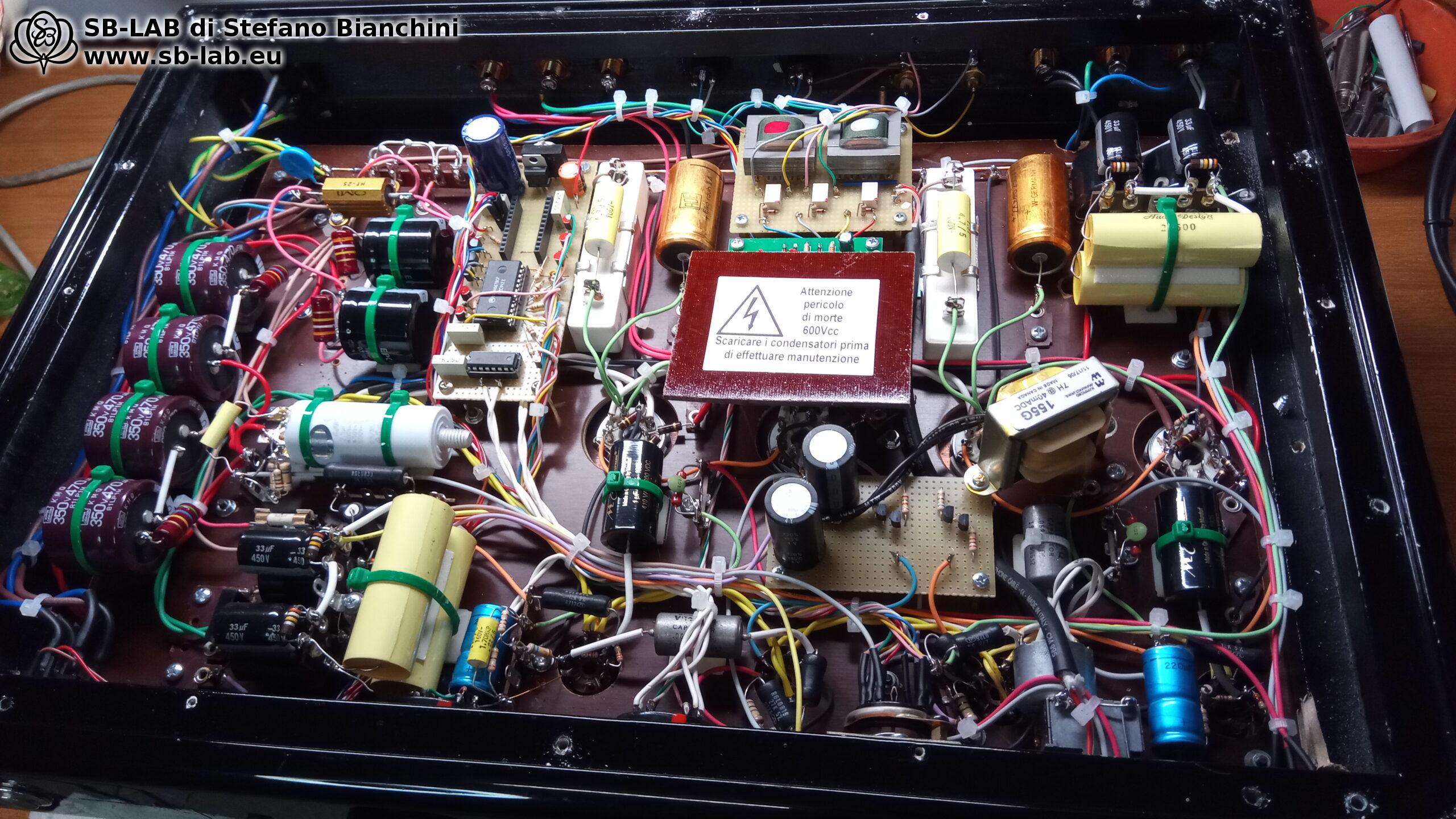
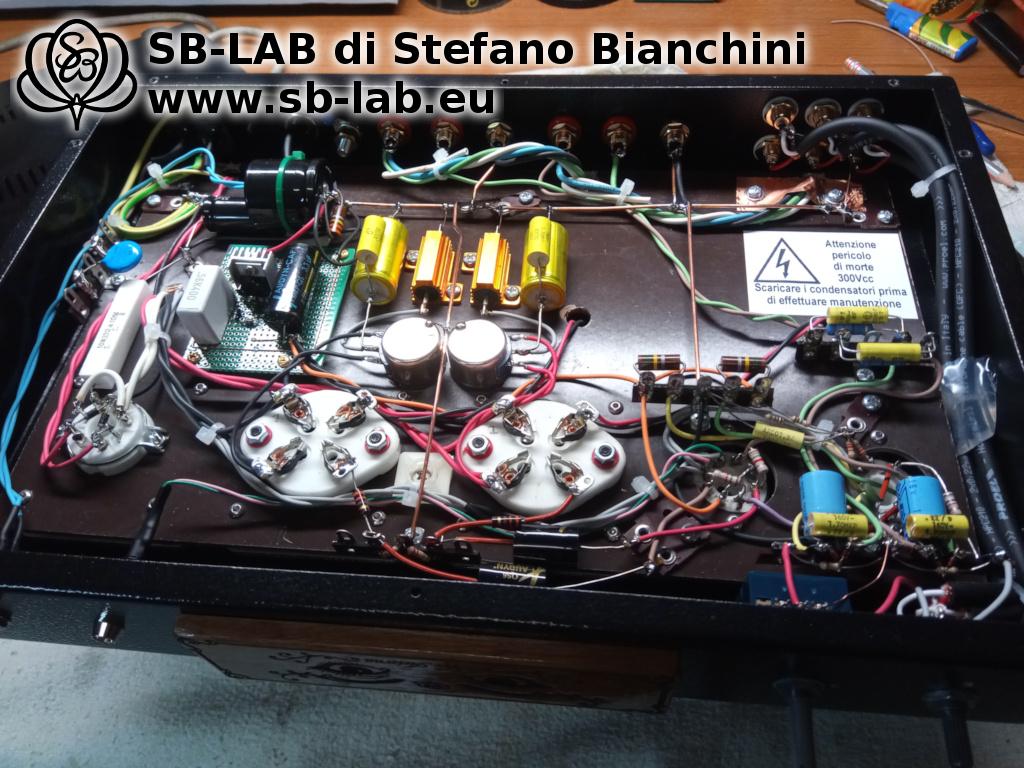
In the following photo you can see the complete wiring of the circuit, done strictly by hand, with careful attention to grounding paths, separation between signal and power, and an orderly, functional aesthetic. Every component was chosen for reliability, electrical characteristics, and sonic coherence, avoiding excessive fads as well as bargain-bin solutions.
Finally, the personal touch: the decorative front effigy. I laser-engraved a small piece of Italian walnut, cut from an ~80-year-old board, with an evocative decoration that echoes rococo style and the nocturnal mystery of the device’s name. At the center, the name Nyx Aeterna, accompanied by the SB-LAB logo. A signature, a statement of identity. An amplifier is not judged only by how it sounds, but also by how it tells its own story, even before the music begins.

Instrument measurements – Concrete data to support the listening

Nyx Aeterna is not just aesthetic and timbral suggestion: behind the craftsmanship and elegance of the sound lies a technically solid design, confirmed by instrument measurements carried out with laboratory equipment.

  • Undistorted RMS power: 3 watts
  • Clipping power: 3.7 watts
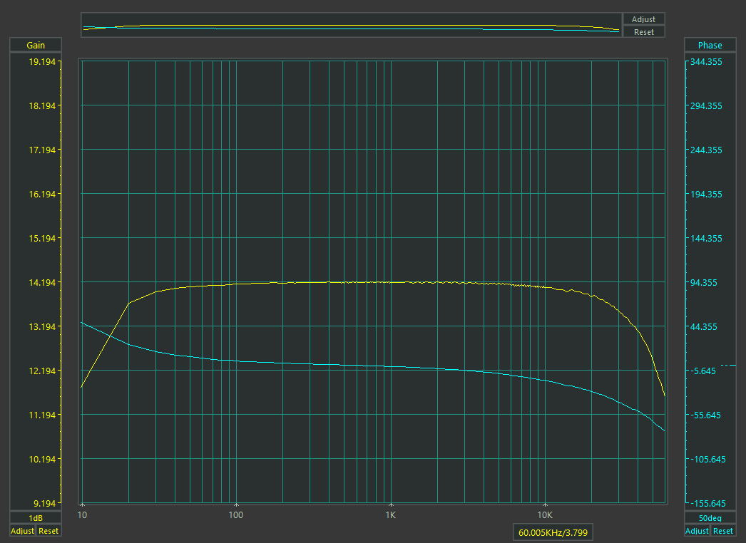
  • Bandwidth at -1 dB: from 18 Hz to 38 kHz, a wide, well-extended response that delivers body and detail even to the most complex recordings
  • Damping factor: 4.4 — a balanced value that ensures good control of reactive loads without sacrificing musicality
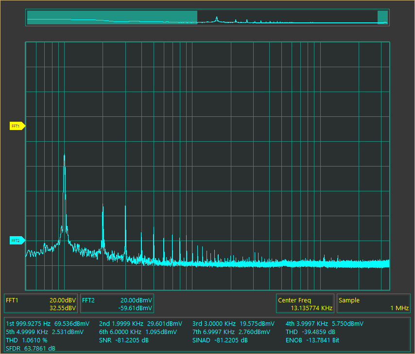
  • THD @ 1 watt: 1% — a natural, pleasant harmonic distortion, perfectly in line with the single-ended triode philosophy
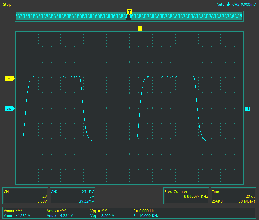
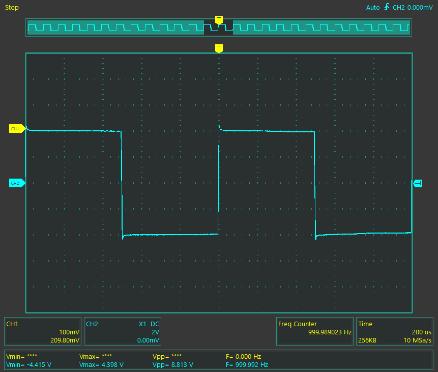
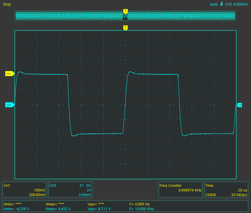
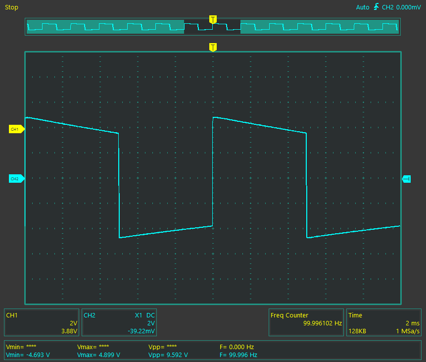
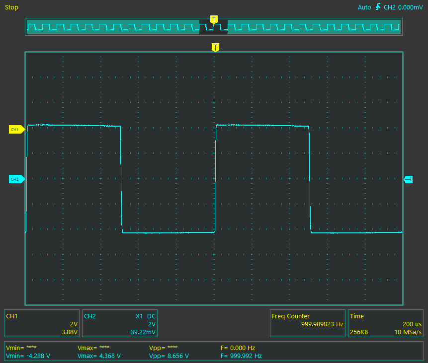
To complete the picture, the square waveforms at 100 Hz, 1 kHz, and 10 kHz show a well-controlled response, free from excessive resonances or phase shifts. The behavior of the output transformer is stable, with no marked overshoot, and with crisp, symmetrical transients — evidence of the high design and build quality of the magnetic section.
Nyx Aeterna – The end of one journey, the beginning of another

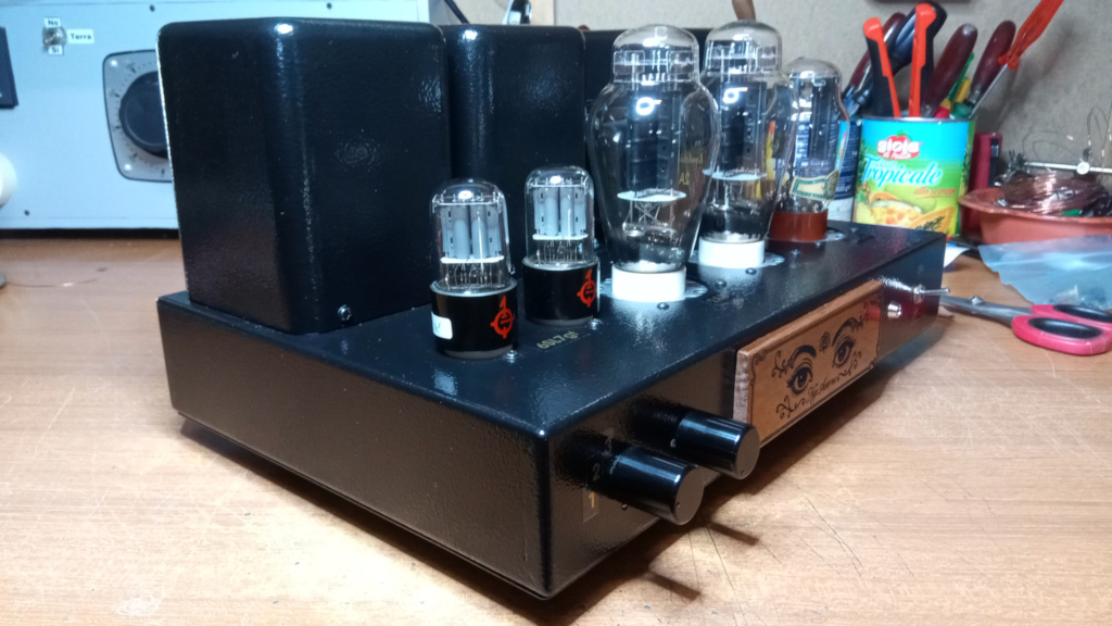
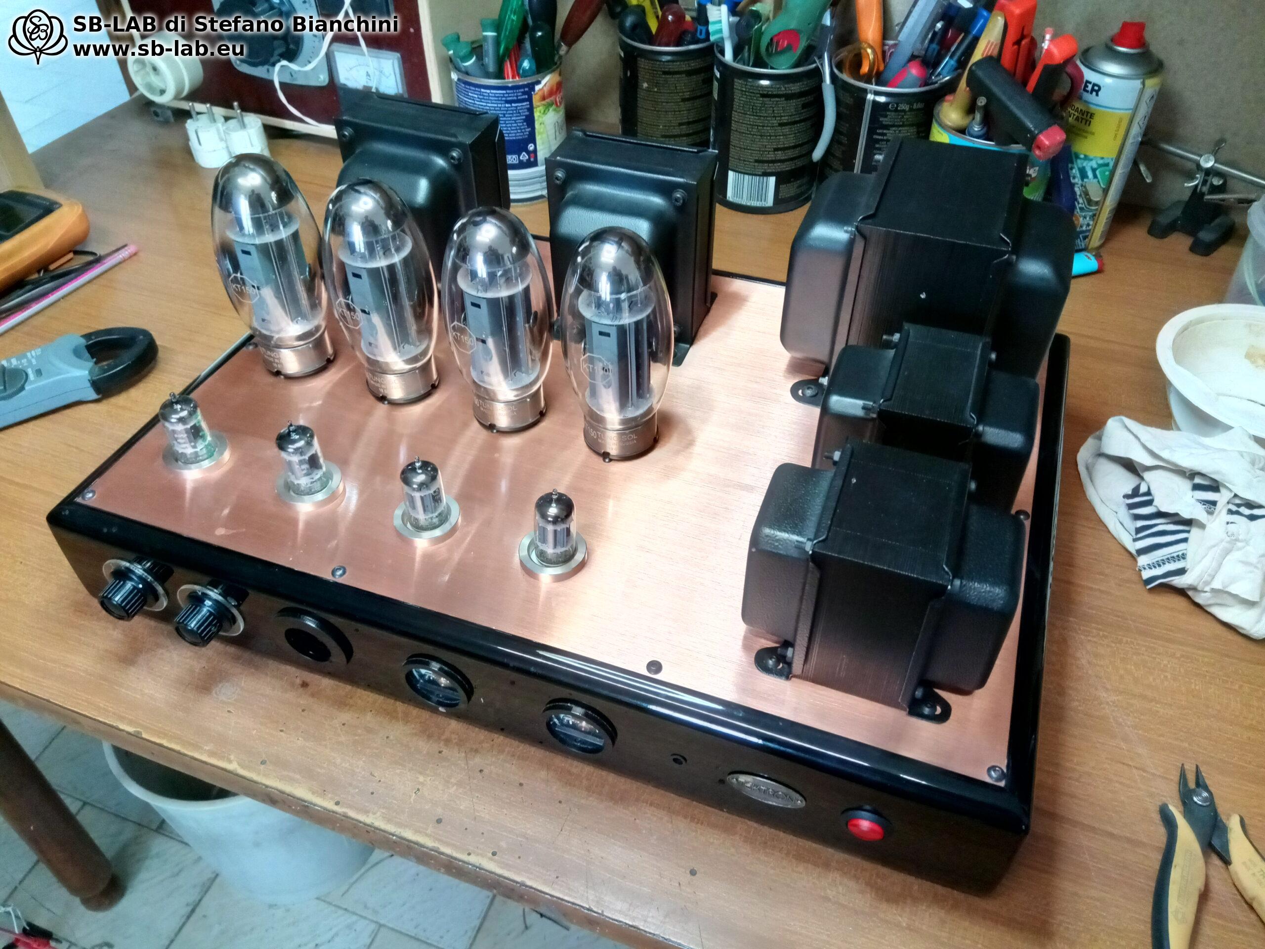
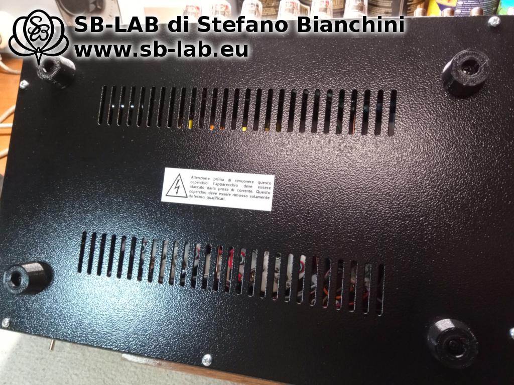
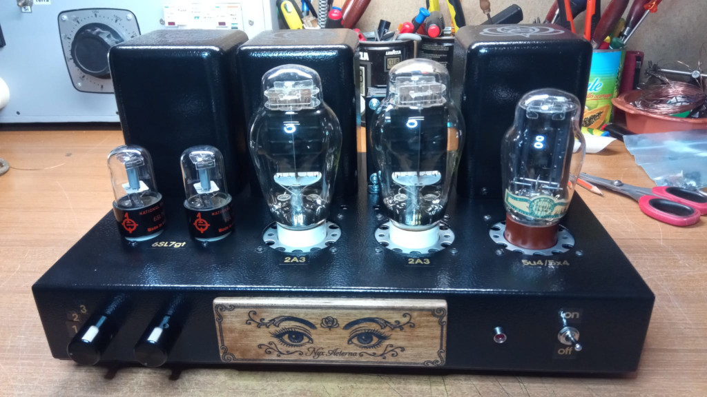
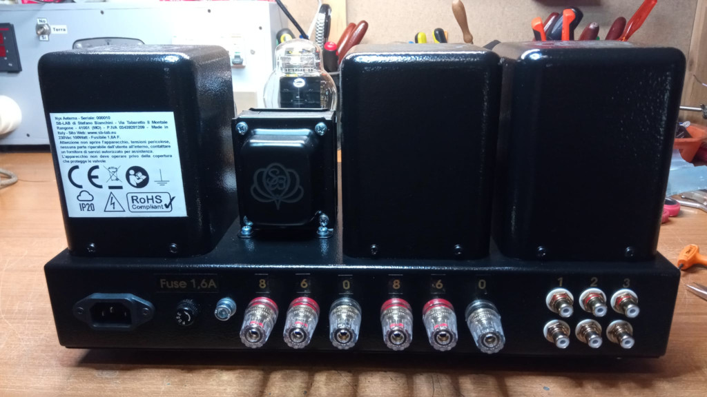
In the final images you can admire Nyx Aeterna in its finished form: elegant, solid, refined in the details. The device comes with CE marking, an instruction manual, a declaration of conformity, and a 2-year warranty, like any object designed and built with technical care and artisanal responsibility.
>>> But Nyx Aeterna is not just a one-off. It is also a possibility. <<<

If you have one of these little Chinese 2A3 amplifiers at home — perhaps forgotten for years, with marred paint and a hum you never got around to fixing — know that it can be reborn. Even if it’s off, even if you no longer use it. Entrust it to me, and it will become something completely different: not an upgrade, not a tweak, but a new creature. A Nyx Aeterna!

And if you’re starting from scratch or you’re a DIY builder, note that the complete set of transformers designed specifically for this circuit (power, output, choke) is available as a premium schematic along with the support needed to build your own version of the project.

Continue reading...

Leave a Reply

This site uses Akismet to reduce spam. Learn how your comment data is processed.

Tone Stove: A Class A Push-Pull Amplifier with 2A3 Tubes

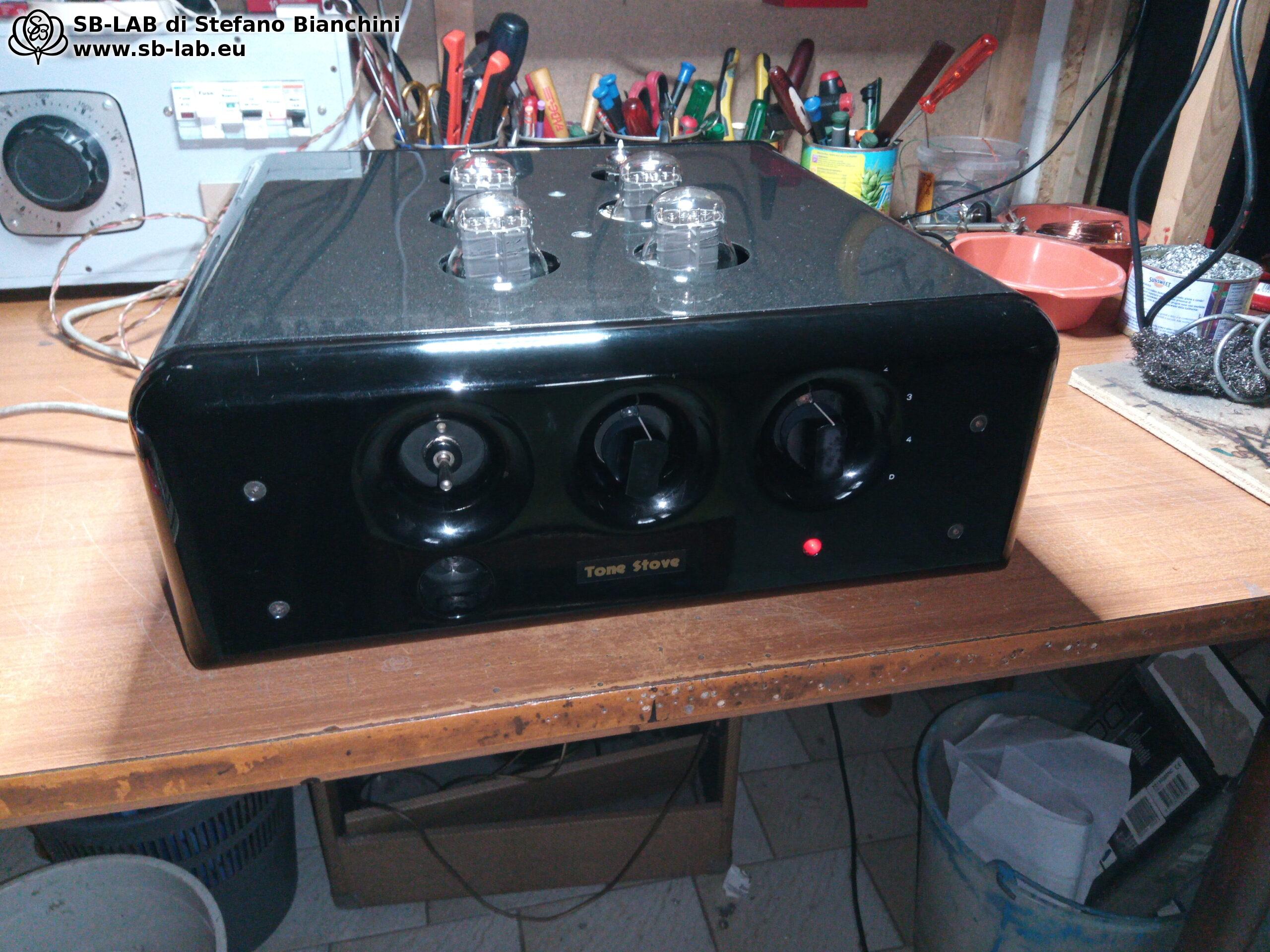
I was brought an old amplifier that, at first glance, looked like a relic from the past. It was a push-pull with 2A3 tubes, originally driven by ECC88 tubes, but over time it had lost all its glory. The amplifier had been abandoned in a cellar, where its condition had deteriorated. The owner, after finding it, decided to have it repaired. However, his story about the crackling channel didn’t prepare me for what I discovered.

The First Encounter with the Wreck

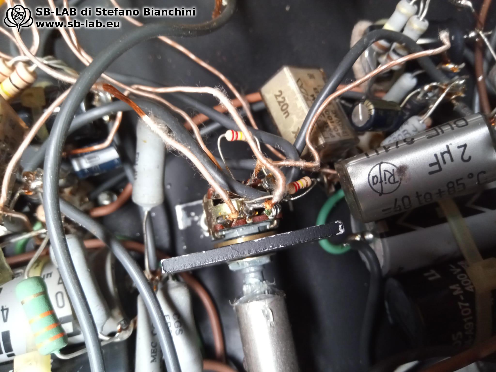
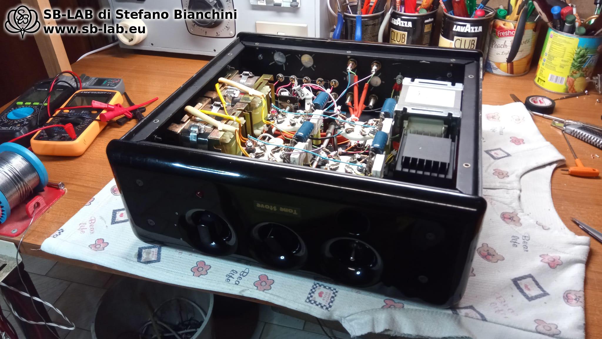
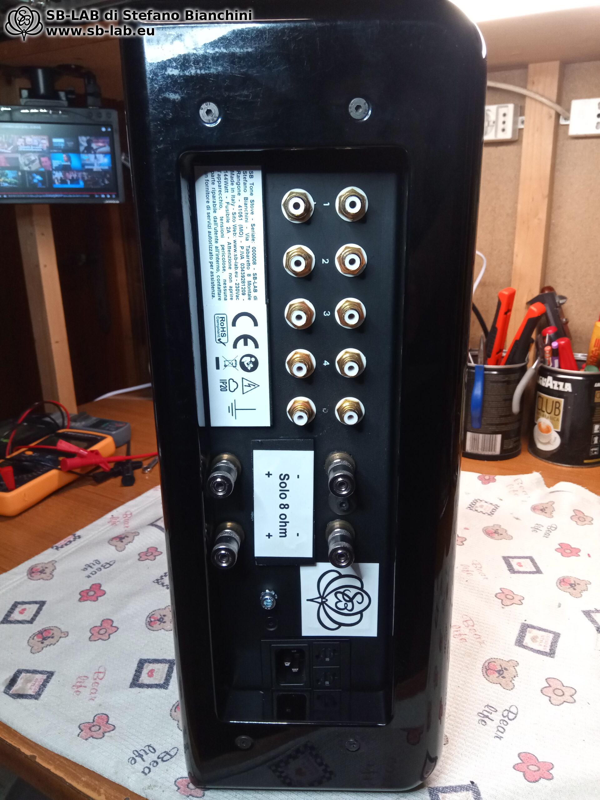
When the amplifier was switched on, the result was not exactly encouraging. One channel oscillated on its own at 64 kHz, while the other delivered barely 0.4 watts. Once I removed the cover and looked at the circuit, it was clear that the amplifier needed a complete overhaul. The photos I show testify to the state of the chassis and the internals, which were heavily compromised. At that moment, I realized the only way forward would be to completely dismantle it and rebuild it from scratch.

From Dismantling to Design

I started by emptying the shell, carefully cleaning the chassis, which had a strong smell of mold due to its time in the cellar. Once the cleaning was completed, I designed a new circuit that was compatible with the existing chassis, keeping the original output transformers. The choice was to use four 2A3 tubes and two noval tubes for the various stages of the circuit.

One detail I had to face was the use of Lundahl LL1621/P-P interstage transformers. According to the datasheet, these transformers could not be driven by a single-ended stage, but only by a push-pull stage. Despite being an integral part of the original amplifier, after reflecting for two days, I decided to eliminate them.

In their place, I opted for a cathodyne phase inverter based on an ECC82, one triode for each pair of 2A3s, while for the input tube I used an ECC83. Although I had considered the idea of using a long-tail inverter, the need for an additional noval socket led me to choose the simpler, more practical solution.

Power Supply and Biasing: Crucial Details

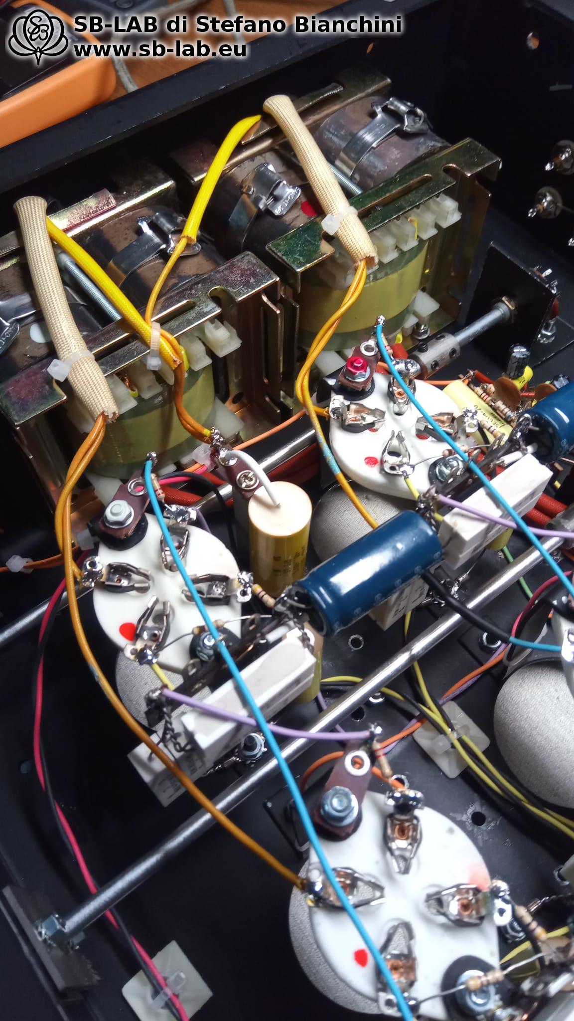
A fundamental aspect of the project was the power supply for the 2A3 tubes. I decided to power them with alternating current, with four dedicated secondaries for each of the four 2A3s. This approach allowed me to separate the filaments, avoiding interference between the tube biases. I chose to implement a self-balancing bias following the Blumlein method, to perfectly balance the bias of each pair of 2A3s. This not only ensured an even distribution of current but also prevented the output transformers from being saturated by possible DC currents, achieving greater efficiency and uniform tube life.

To achieve this, I had to replace the power transformer with one specifically designed to meet the project’s requirements. Using advanced techniques, going beyond the use of simple resistors for filament centering (allow me to keep my secrets), I managed to eliminate any hum from the amplifier.

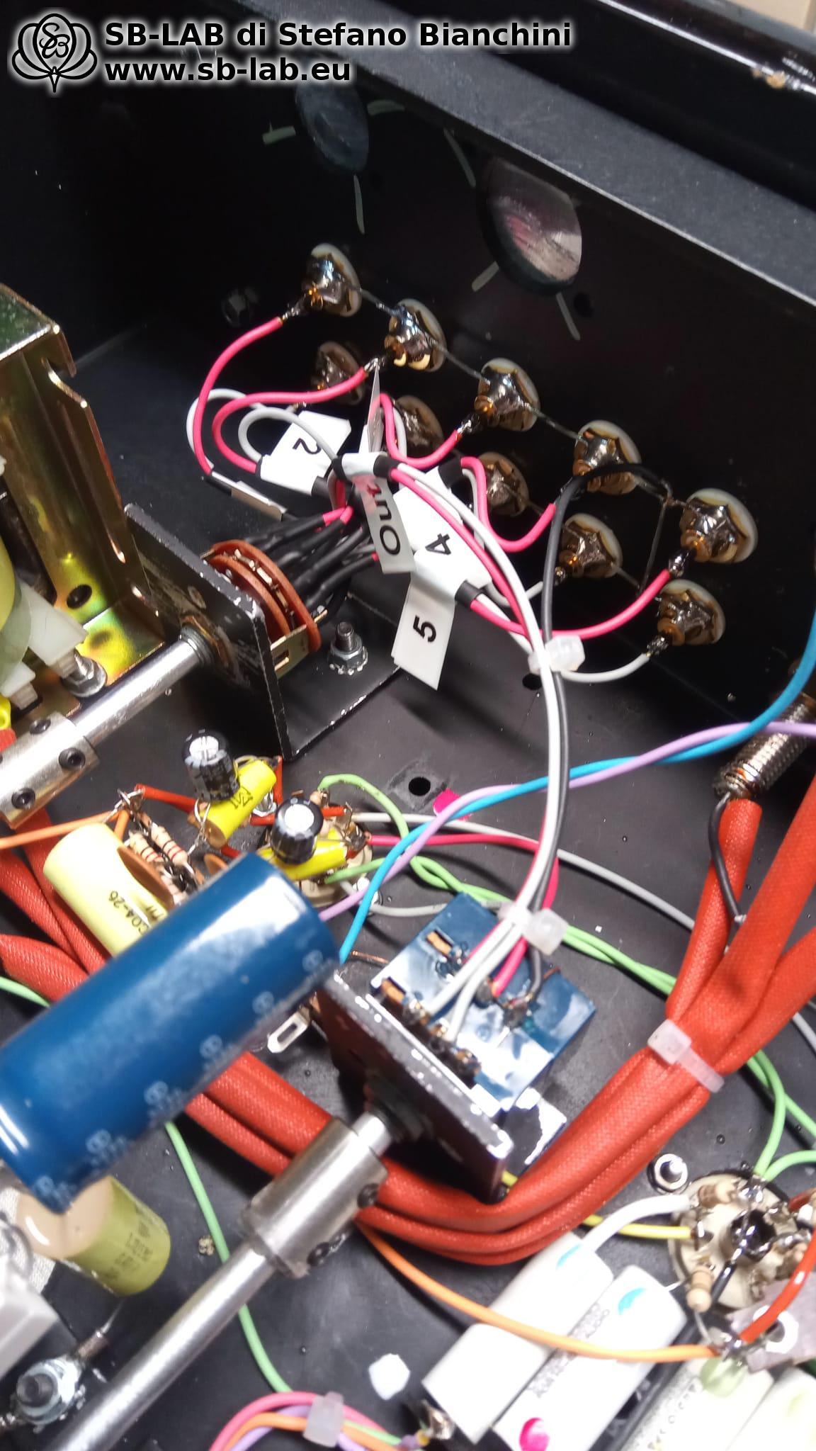
All components are firmly fixed on both sides to an anchoring point. No component relies on the support of adjacent ones. Every anchor point is screwed, including the nylon square pads, to which I fastened the wires using ties. Even these pads are screwed, with no adhesives used to secure components.

The filaments of the ECC83/82 tubes are also powered by AC, a solution I’m quite proud of.

The Final Result: Performance and Sound Quality

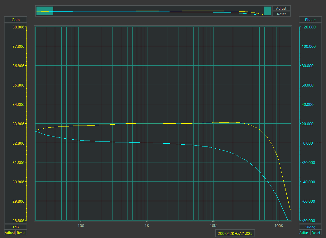
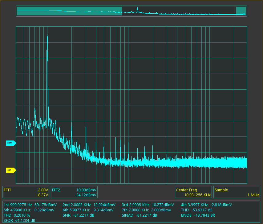
After assembling the entire circuit, the result was immediately satisfying and hum-free. The two pairs of 2A3s work in push-pull class A, delivering 6 watts RMS per channel, with a damping factor of 4.6 and a total harmonic distortion (THD) of about 0.18% at 1 watt. The resulting sound is extremely clean, powerful, and free from unwanted noise.

Bandwidth 20Hz -0.4dB / 75kHz -1dB

THD

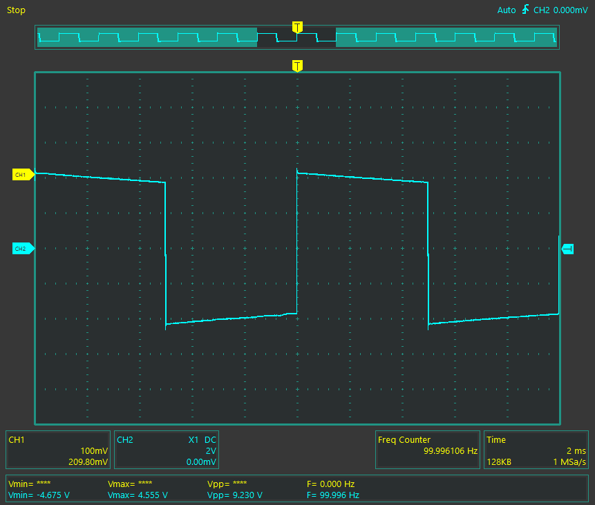
Square Waves at 100Hz / 1kHz / 10kHz

The Tone Stove project was not only a technical challenge but also a true reinterpretation of the classic tube amplifier, optimized for maximum audio quality, without compromises or ideologies.

Continue reading...

Leave a Reply

This site uses Akismet to reduce spam. Learn how your comment data is processed.

Anansi Project: Single Ended Parallel Amplifier with KT150 Tubes

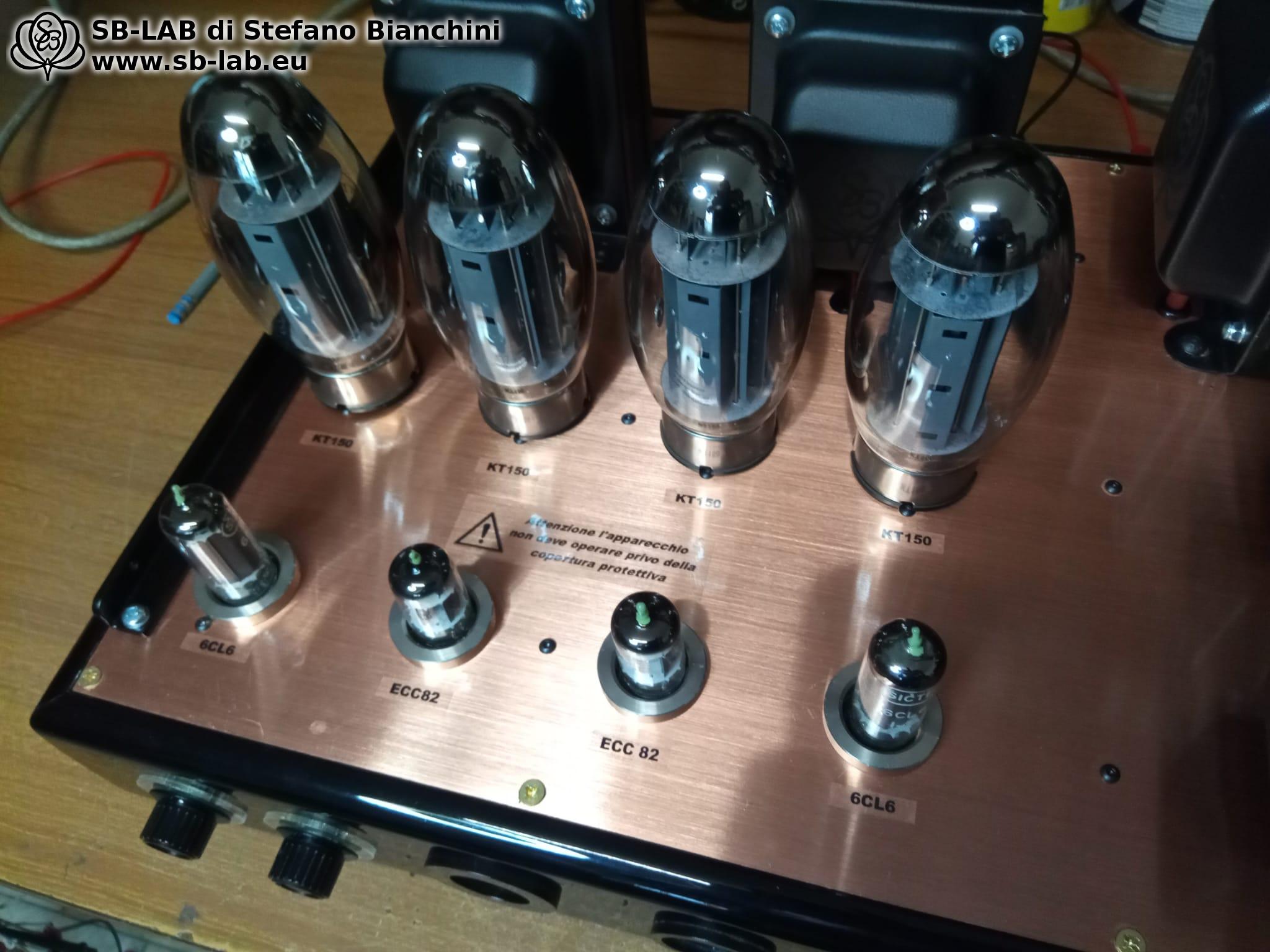
The unit, which I christened Anasi, was entrusted to me by its owner due to a series of faults. The problems included tube sockets that did a poor job of retaining the tubes, crosstalk and interference between channels: a disruptive listening experience in which inactive channels could be heard in the background even when switching channels. In addition, the balanced input turned out to be a simulation with the phase shorted, essentially operating as a standard unbalanced channel.

Opening the unit was eye-opening… The customer insisted on a complete rebuild, practically turning the device into a brand-new one, with very few elements of the original retained. Personally, I would not have taken on this job if it hadn’t been for the client’s strong request. Don’t get me wrong: the customer is always right, and designing a new circuit and reusing the framework were still fun and stimulating experiences. I carried out this work in my spare time, putting in passion and effort to achieve a satisfying result. When the unit was delivered to me, I immediately took a series of detailed photos and recorded short videos to accurately document its original condition.

The birth of Anansi

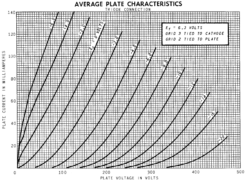
After completely disassembling the original amplifier down to the last screw, the idea of what Anansi should be began to take shape. Anansi retains the basic concept of the unit that was scrapped, namely a Parallel Single-Ended with KT150 tubes wired as triodes, 25 watts RMS per channel. The original unit used an ECC82 with sections in parallel to drive the two KT150s. However, preferring to avoid tubes with parallel sections and wanting a robust drive for the KT150s, I opted to use the 6CL6 tube wired as a triode. Below are the curves of the 6CL6 in triode mode; it has a mu of 20 and a decidedly higher current-delivery capability than an ECC82.

This tube was implemented as the driver stage, ensuring adequate drive capability for the KT150s. For the input stage, I used the ECC82 configured as a long-tail phase splitter, despite the circuit being single-ended. This solution was adopted to avoid excessive circuit gain.

I also planned to handle the balanced input with coupling transformers, specifically the Split-TL082. These are 3-winding 1:1:1 transformers of 600 ohms, suitable for accepting a balanced input signal and converting it to unbalanced. This solution preserves the benefits of a balanced cable, such as noise rejection, which does not occur if only one phase of the signal is used.

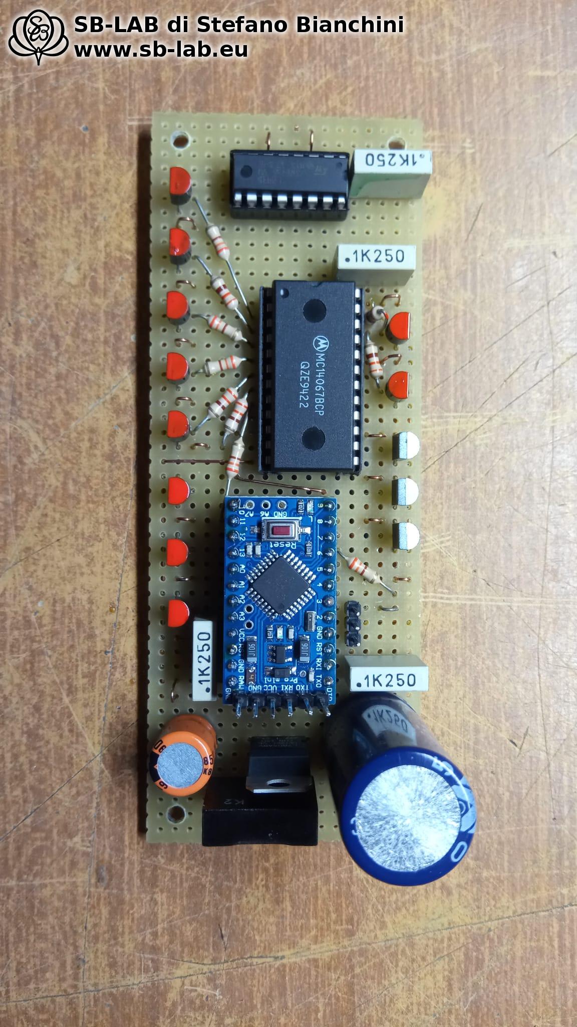
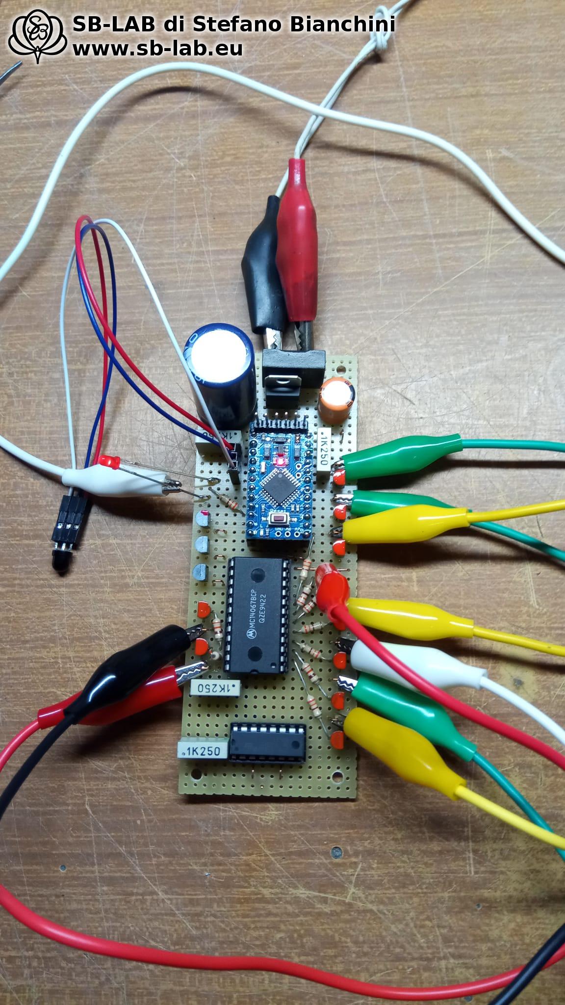
I then decided to eliminate the Chinese remote control board and design a custom Arduino-based board. This not only manages volume control, but also channel switching and driving the Nixie indicator for the active channel. I completely replaced the original transformers, saving only the covers, and designed a new set of power and output transformers. In addition, I calculated a new filter choke with an air gap. The switch originally used for channel selection was converted into a 2-position switch to enable or disable the feedback signal.

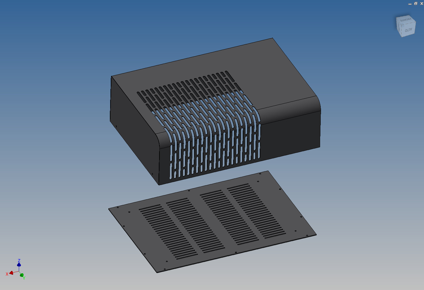
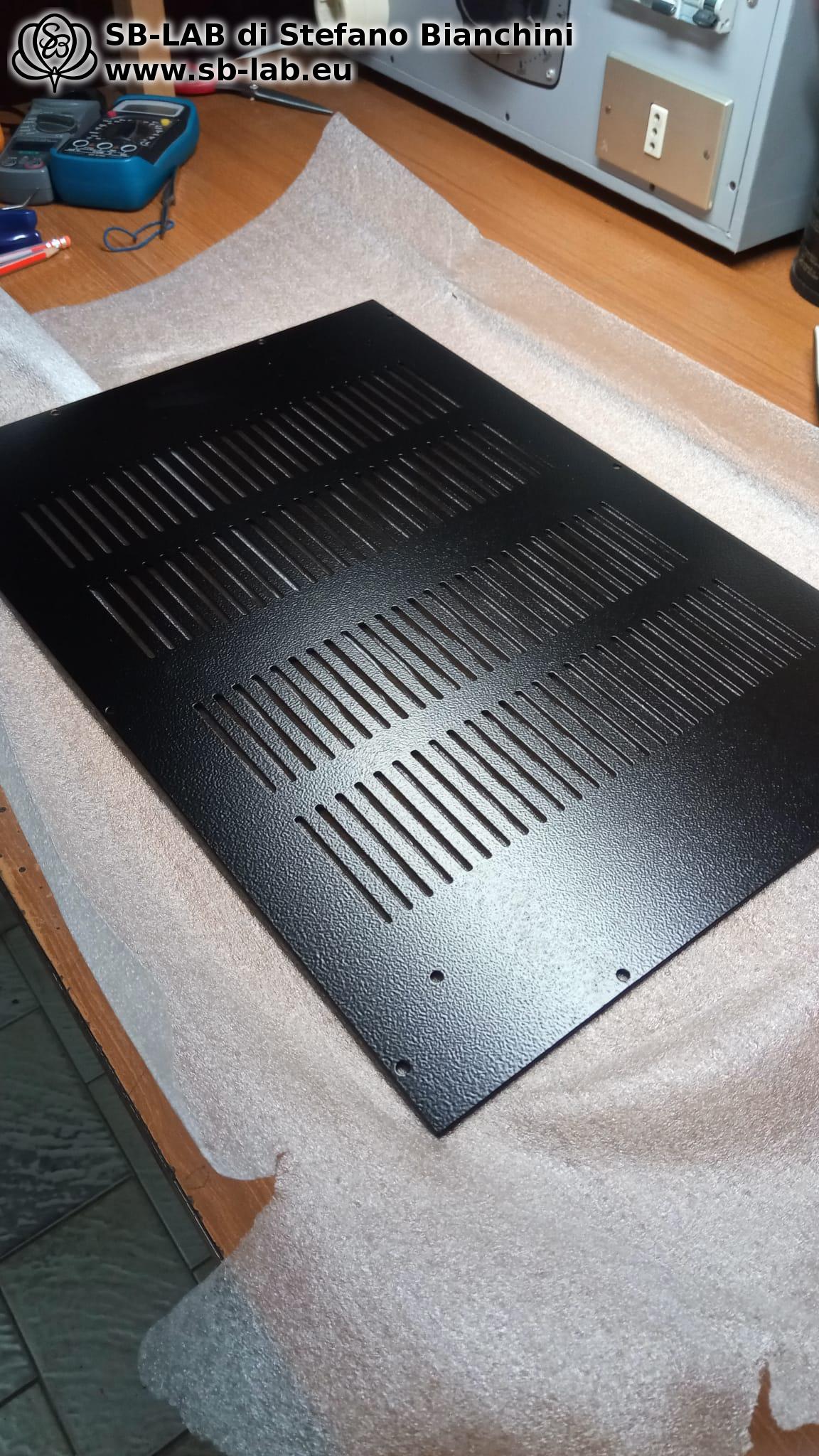
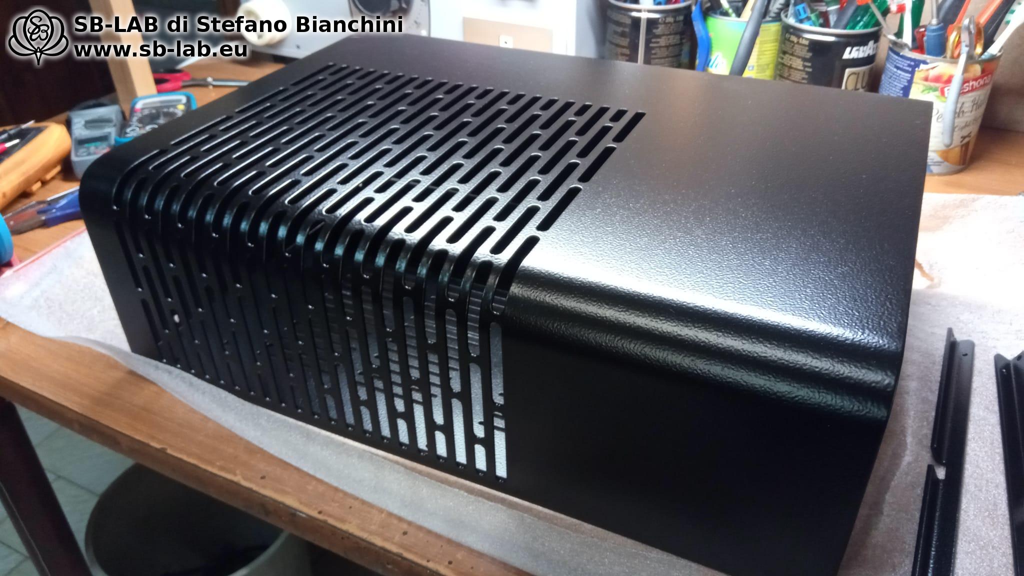
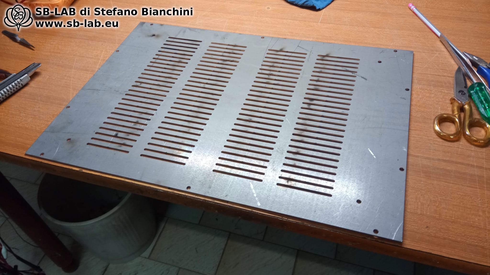
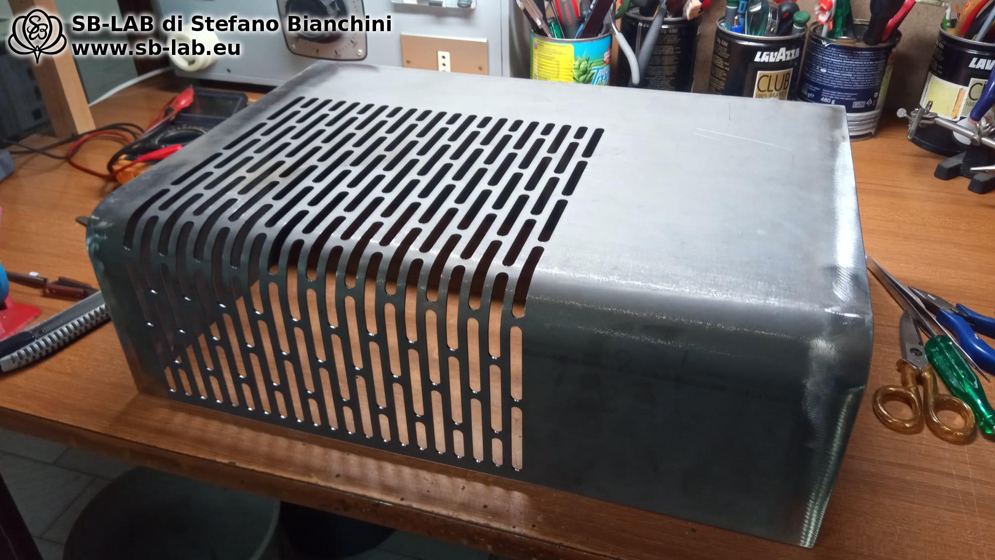
Next, I designed in CAD and had a workshop make an essential steel cover, meant to be firmly fixed to the amplifier body with screws; I continued with the creation of a mounting support for all the wiring, using insulating materials. I then began assembling Anansi’s circuit. During this process, I managed to salvage some parts from the original circuit, including capacitors, anchors, the output tube sockets, the board for the VU meters, the motorized potentiometer, the infrared sensor for the remote control, the speaker connectors and the input RCAs, as well as various screws, washers and nuts, in addition to the original chassis and the copper plate that supported everything.

Assembly in practice

In the photos below, you can see the design process of the sturdy steel cover, the circuit mounting plane made of insulating material, as well as the bottom and mounting supports:

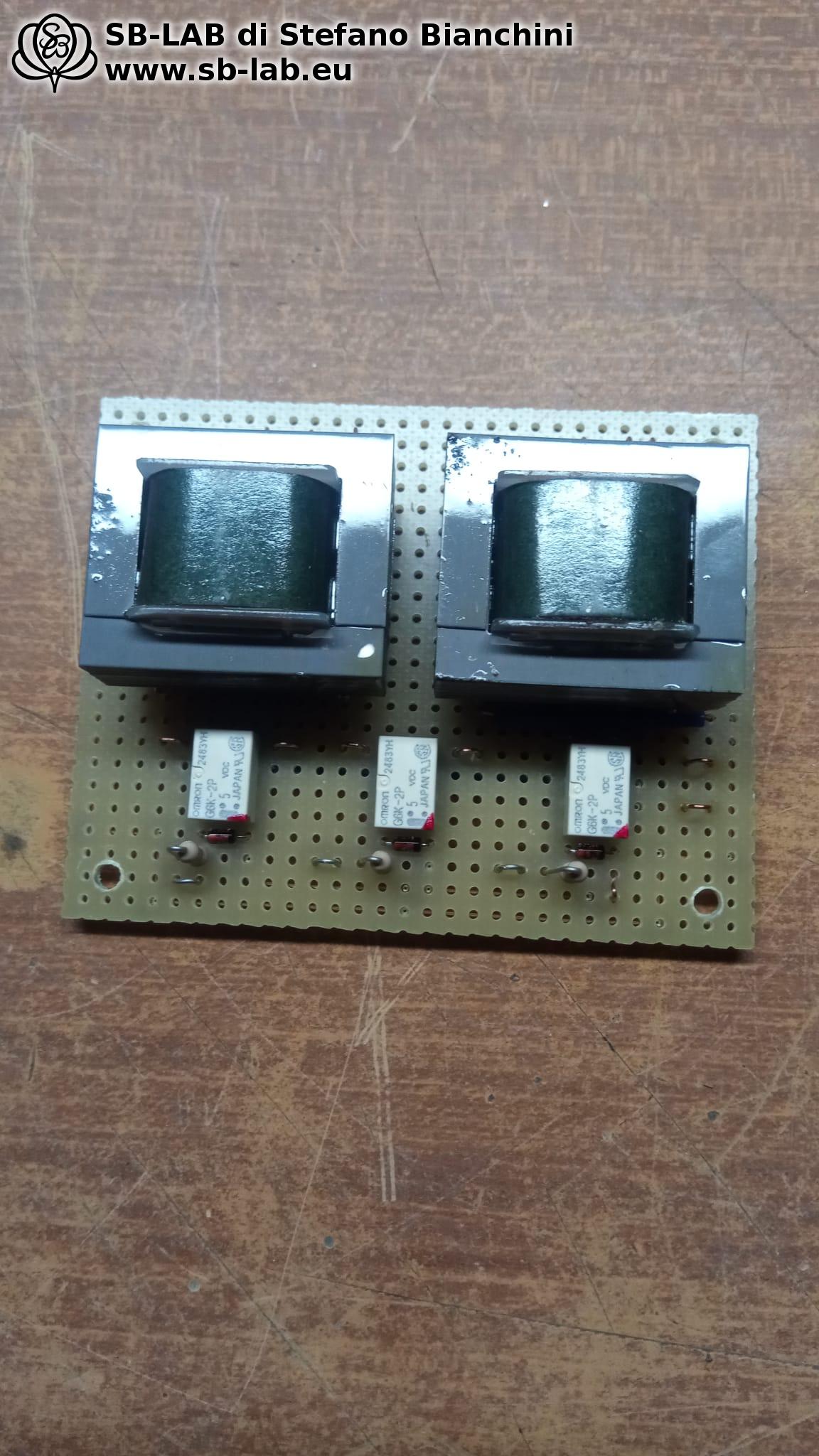
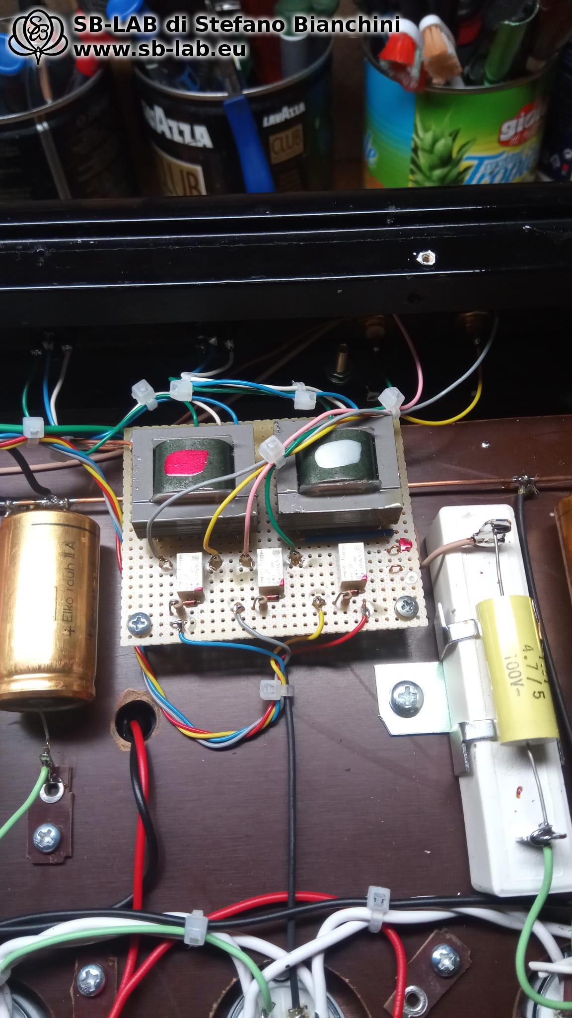
In the following photos I show the construction of the two audio transformers dedicated to the balanced input, together with the relay board that manages the 3 total inputs with signal-grade relays, equipped with silver contacts sealed in an inert atmosphere. The goal of this approach is to minimize the length of audio connections to avoid interference between signals, while always ensuring a perfect contact. This is in stark contrast to bronze switches exposed to air and humidity which, over time, can oxidize, and to long, unshielded wires running in parallel suspended from a piece of iron wire.
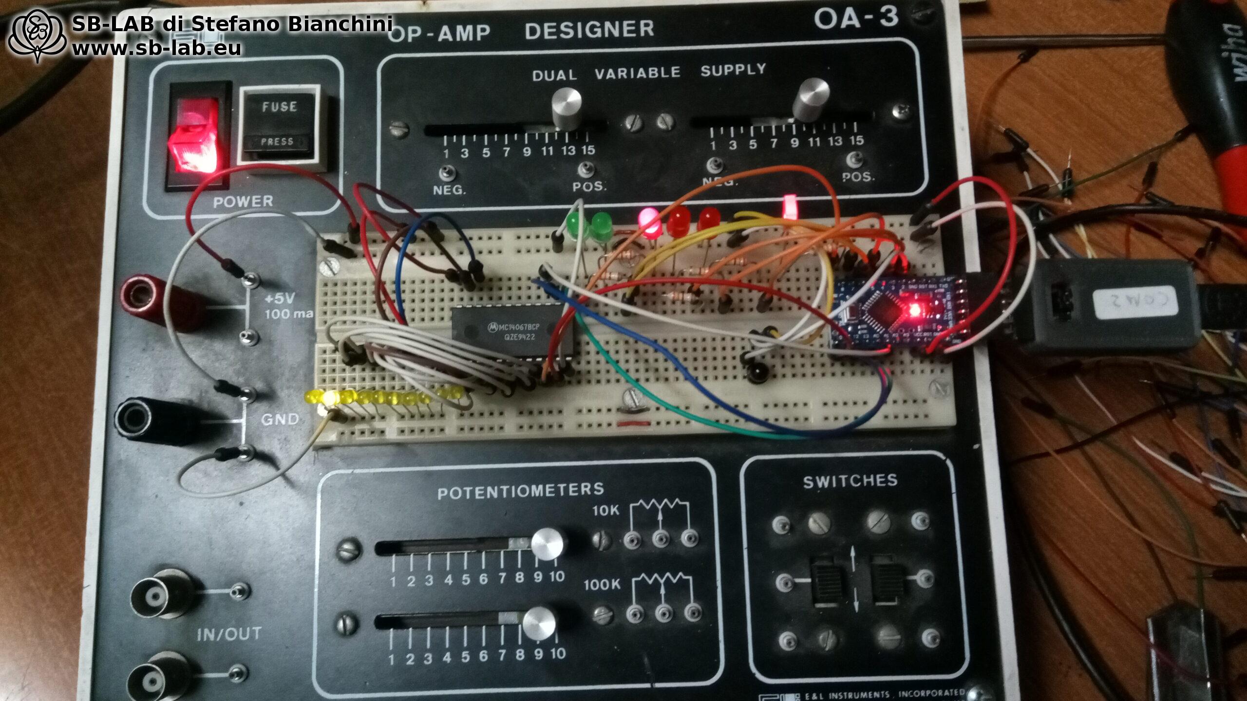
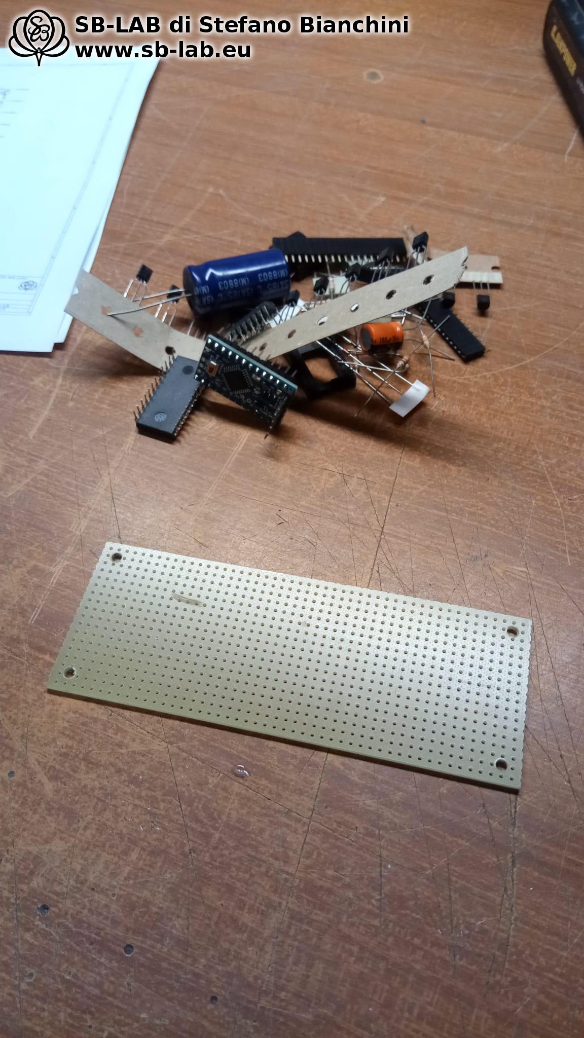
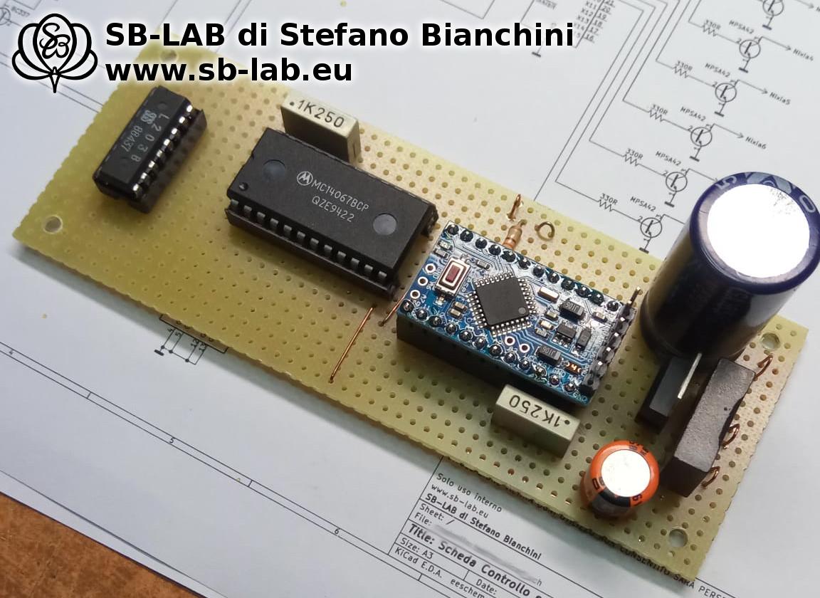
In the next set of photos and videos, I show the prototyping of the Arduino-based control board, and the source code of the control program is available for anyone who wants to explore it.

/*
 * Firmware 1.0 per Ricevitore Remoto Tektron - Progetto PSE-KT150
 * Autore: Stefano Bianchini
 * Azienda: SB-LAB (www.sb-lab.eu)
 * Licenza: GNU General Public License version 2 (GPL-2.0)
 *
 * Descrizione:
 * Questo firmware controlla le funzioni di un amplificatore a valvole KT150 single-ended parallelo,
 * ricostruito utilizzando il telaio di un amplificatore Tektron demolito. Il programma accetta input dal
 * telecomando infrarossi originale Tektron. Gestisce la fase di accensione dell'amplificatore impostando
 * un periodo di muto pre-riscaldamento, controlla il cambio dei canali e l'aggiustamento del volume tramite
 * gli input del telecomando e visualizza il canale attualmente selezionato su un tubo Nixie originariamente
 * integrato nell'amplificatore Tektron. Il programma include una funzione per prevenire l'avvelenamento del
 * catodo del tubo Nixie.
 *
 * Description:
 * This firmware controls the functions of a KT150 single-ended parallel valve amplifier,
 * reconstructed using the chassis of a Tektron remolito amplifier. The program accepts input from the
 * original Tektron infrared remote control. It manages the amplifier's power-up phase by setting a
 * pre-heating mute period, controls channel changes and volume adjustments via remote control inputs, and
 * displays the currently selected channel on a Nixie tube originally integrated into the Tektron amplifier.
 * The program includes a function to prevent cathode poisoning of the Nixie tube.
 * 
 * Nota sulla Licenza / License Notice:
 * Questo software è distribuito con la Licenza Pubblica Generale GNU versione 2 (GPL-2.0).
 * Ciò significa che sei libero di utilizzare, modificare e distribuire questo software in base ai termini
 * della GPL-2.0. Ogni modifica apportata al codice deve essere resa pubblica e deve includere una nota
 * indicante le modifiche effettuate. Ogni distribuzione del codice deve includere questa nota sulla licenza
 * e preservare i riferimenti all'autore originale.
 *
 * This software is distributed under the GNU General Public License version 2 (GPL-2.0).
 * This means that you are free to use, modify, and distribute this software under the terms of the GPL-2.0.
 * Any modifications made to the code must be made public and include a note indicating the changes made.
 * Any distribution of the code must include this license notice and preserve the references to the original author.
 *
 * Contattami / Contact Me:
 * Per eventuali domande o miglioramenti al codice, puoi contattarmi all'indirizzo:
 * https://www.sb-lab.eu/mandami-una-e-mail/
 */

#include <Arduino.h>
/* compilare in presenza della libreria IRRemote 4.20 */
#include <IRremote.hpp>

/* pin associato al ricevitore infrarosso */
#define IR_RECEIVE_PIN 2

/* Adatta il ricevitore IR, un valore di 20 è consigliato per il ricevitore recuperato dal tektron, valore diversi causano ricezione di dati casuali */
#define MARK_EXCESS_MICROS 20
/* definisco le stringhe che rappresentano i tasti */
#define tasto_meno 0xF6093A00
#define tasto_piu 0xEA153A00
#define tasto_on_off 0xF20D3A00
#define ripeti 0
/* definisco i pin dei rele' degli ingressi */
#define rel1 3
#define rel2 4
#define rel3 5

/* pin che controllano il demultiplexer MC14067b */
#define nix_A 9     /* pin 10 MC14067b */
#define nix_B 10    /* pin 11 MC14067b */
#define nix_C 11    /* pin 14 MC14067b */
#define nix_D 12    /* pin 13 MC14067b */
#define nix_EN 14   /* pin 15 MC14067b */

/* pin che controllano il driver motore L293D */
#define motor_up 8
#define motor_down 7

/* led integrato nel pulsante di accensione */
#define power_led 6

/* codici telecomando */
unsigned long value;
unsigned long old_value;

/* memoria canali*/
unsigned char canale = 1;

/* variabili per timer non bloccante usato per il controllo fluido del motore */
unsigned char vol = 0;
unsigned int timer = 0;
/* costante per fludita' motore del volume */
#define nbdelay 12288

/* impostazioni del timer per la funzione disossida */
unsigned long ultimoRichiamo = 0;
unsigned long intervallo = 60000;  /* Intervallo di 1 minuti */

/* impostazione del timer mitigazione */
unsigned long ultimoRichiamo2 = 0;
unsigned long intervallo2 = 3000;  /* Intervallo di 3 secondi */

void setup()
{
    pinMode(LED_BUILTIN, OUTPUT);
    pinMode(power_led, OUTPUT);
    pinMode(rel1, OUTPUT);
    pinMode(rel2, OUTPUT);
    pinMode(rel3, OUTPUT);
    pinMode(motor_up, OUTPUT);
    pinMode(motor_down, OUTPUT);
    pinMode(nix_A, OUTPUT);
    pinMode(nix_B, OUTPUT);
    pinMode(nix_C, OUTPUT);
    pinMode(nix_D, OUTPUT);
    pinMode(nix_EN, OUTPUT);
    /* Abilita il lampeggio del led integrato che indica la ricezione di qualcosa, utile per debug */
    IrReceiver.begin(IR_RECEIVE_PIN, ENABLE_LED_FEEDBACK);
    /* accende il led nel pulsante power */
    digitalWrite(power_led, HIGH);
    /* nixia spenta */
    digitalWrite(nix_EN, HIGH);
}

/* funzione che abbassa il volume quando si esce da un canale */
int fade_out()
{
  digitalWrite(motor_down, HIGH);
  /* durante l'uscita dal canale lampeggia il numero sulla nixia */
  for (char i = 0; i < 10; i++)
    {
      digitalWrite(nix_EN, HIGH);
      delay(500);
      digitalWrite(nix_EN, LOW);
      delay(500);
    }
  digitalWrite(motor_down, LOW);
}

/* funzione che rialza il volume quando si entra in un nuovo canale */
int fade_in()
{
  digitalWrite(motor_up, HIGH);
  delay(2000);
  digitalWrite(motor_up, LOW);
}

int cambia_canale()
{
  if(canale > 3) { canale = 1; }
  if(canale == 1) { fade_out(); digitalWrite(rel1, HIGH); digitalWrite(rel2, LOW); digitalWrite(rel3, LOW); scrivi_nixia(canale); fade_in(); }
  if(canale == 2) { fade_out(); digitalWrite(rel1, LOW); digitalWrite(rel2, HIGH); digitalWrite(rel3, LOW); scrivi_nixia(canale); fade_in(); }
  if(canale == 3) { fade_out(); digitalWrite(rel1, LOW); digitalWrite(rel2, LOW); digitalWrite(rel3, HIGH); scrivi_nixia(canale); fade_in(); }
  canale ++;
  ir_mon();
  delay(250);
}

/* Slampeggia il led power */
int ir_mon()
{
  digitalWrite(power_led, LOW);
  delay(50);
  digitalWrite(power_led, HIGH);
}

int motore(char tasto)
{
  if (tasto == '+' && vol == 0) /* Tasto Vol + */
    {
      ir_mon();
      vol = 1;
    }
  if (tasto == '+' && vol == 1) /* Tasto Vol + con pot in marcia */
    {
      ir_mon();
      timer = 0;
    }
  if (tasto == '-' && vol == 0) /* Tasto Vol - */
    {
      ir_mon();
      vol = 2;
    }
  if (tasto == '-' && vol == 2) /* Tasto Vol - con pot in marcia */
    {
      ir_mon();
      timer = 0;
    } 
}

/* questa funzione accetta in ingresso un valore da 0 a 16 e imposta i 4 bit all'ingresso del demultiplexer */
int scrivi_nixia(unsigned char cifra)
{
  digitalWrite(nix_A, (cifra & 0b0001) ? HIGH : LOW);
  digitalWrite(nix_B, (cifra & 0b0010) ? HIGH : LOW);
  digitalWrite(nix_C, (cifra & 0b0100) ? HIGH : LOW);
  digitalWrite(nix_D, (cifra & 0b1000) ? HIGH : LOW);
}

/* visto che la nixia per la maggiorparte del tempo visualzzera' sempre e solo i numeri 1-2-3 e questo potrebbe causare avvelenamento dei catodi
 * con la compromissione della nixia stessa, questa funzione richiamata ciclicamente fa una scansione
 * di tutte le cifre della nixia per evitarne il deterioramento precoce. */
int disossida()
{
  for (unsigned char i = 0; i < 10; i++) { scrivi_nixia(i); delay(125); }
  /* alla fine della scansione ripristina la cifra corretta che corrisponde al canale correntemente attivato */
  scrivi_nixia(canale - 1);
}

void loop()
{
  /* procedure di partenza */
  /* all'accensione gli ingressi sono tutti e 3 disattivati faccio lampeggiare lo zero sulla nixia per 40 secondi in attesa del riscaldamento
   * mentre lampeggia abbasso anche il volume a zero per evitare uragani alla partenza */
  scrivi_nixia(0);
  for (char i = 0; i < 40; i++)
    {
      digitalWrite(nix_EN, HIGH);
      delay(500);
      digitalWrite(nix_EN, LOW);
      delay(500);
    }
  digitalWrite(nix_EN, LOW);
  canale = 1;
  cambia_canale();
  /* l'amplificatore e' avviato, inizio un ciclo infinito dove leggo gli input del telecomando */
  for(;;)
  {
    /* Questa e' la funzione non bloccante che attiva ciclicamente la funzione per disossidare la nixia */
    unsigned long tempoCorrente = millis();
    /* Verifica se è passato un minuto dall'ultimo richiamo */
    if (tempoCorrente - ultimoRichiamo >= intervallo)
      {
        /* Richiama la funzione disossida */
        disossida();
        /* Aggiorna il tempo dell'ultimo richiamo */
        ultimoRichiamo = tempoCorrente;
      }
   /* Nota sul telecomando Tektron:
    * Il telecomando invia ripetutamente comandi zero ("0" ossia ripetizione) dopo l'invio del comando effettivo.
    * Questo comportamento, sebbene non ottimale, è una caratteristica intrinseca del telecomando Tektron.
    * Il problema principale sorge quando si preme un tasto e, per qualsiasi motivo, il primo impulso
    * non viene ricevuto correttamente, ma successivamente vengono ricevuti i comandi di ripetizione.
    * Questo può causare un comportamento indesiderato, poiché il programma interpreta erroneamente
    * gli zeri come la ripetizione dell'ultimo comando ricevuto correttamente anche se diverso dal tasto effettivamente premuto.
    * Per mitigare questo problema, è stato implementato un timeout di 10 secondi nel programma
    * che interrompe qualsiasi azione in corso se non viene ricevuto alcun comando durante tale periodo.
    * È importante notare che questa mitigazione potrebbe non essere completamente efficace
    * se vengono premuti tasti diversi molto velocemente, perche' finche' non scadono i 3 secondi la variabile old_value non viene azzerata
    * e quindi il problema potrebbe presentarsi, questa mitigazione interrompe anche la corsa del potenziometro del volume in corsa */
    
    /* codice della mitigazione*/
    unsigned long tempoCorrente2 = millis();
    /* Verifica se è passato un minuto dall'ultimo richiamo */
    if (tempoCorrente2 - ultimoRichiamo2 >= intervallo2)
      {
        old_value = 0;
        /* Aggiorna il tempo dell'ultimo richiamo */
        ultimoRichiamo2 = tempoCorrente2;
      }
    /* fine del codice della mitigazione */
    
    if (IrReceiver.available())
      {
        if (IrReceiver.decode())
        {
            /* memorizza il valore RAW nel buffer value */
            value = IrReceiver.decodedIRData.decodedRawData;
            /*  il telecomando manda il codice pulsante solo al primo impulso, dopo continua a inviare degli zero che significano "ripetizione dello stesso
             *  tasto", questa funzione che ricopia il registro value in old_value serve per richiamare l'ultima routines richiamata in caso il codice ricevuto
             *  sia zero */
            if(value == tasto_meno)
              { 
                /* memorizza value in old_value */
                old_value = value;
              }
            if(value == tasto_piu)
              {
                /* memorizza value in old_value */
                old_value = value;
              }
            /* utilizzo il tasto on/off del telecomando per cambiare i canali */
            if(value == tasto_on_off)
              {
                /* memorizza value in old_value */
                old_value = value;
              }
            /* richiamo la funzione legata al tasto premuto memorizzato, gestisco i segnali di ripetizione e discrimino eventuali segnali errati */
            if ((old_value == tasto_meno && value == ripeti) || (old_value == tasto_meno && value == tasto_meno))
              {
                motore('-');
              }
            if((old_value == tasto_piu && value == ripeti) || (old_value == tasto_piu && value == tasto_piu))
              {
                motore('+');
              }
            if(old_value == tasto_on_off && value == tasto_on_off)
              {
                cambia_canale();
              }
            /* prepara il ricevitore per un nuovo ciclo */
            IrReceiver.resume();
        }
    }
  /* funzione per rendere fluido l'andamento del volume con timer non bloccante */
  if(vol == 1 && timer < nbdelay)
    {
      digitalWrite(motor_up, HIGH);
      timer ++;
    }
  if(vol == 2 && timer < nbdelay)
    {
      digitalWrite(motor_down, HIGH);
      timer ++;
    }
  if(timer >= nbdelay)
    {
      digitalWrite(motor_up, LOW);
      digitalWrite(motor_down, LOW);
      vol = 0;
      timer = 0;
    }
  /* Fine funzione timer non bloccante */
  }
}

You can download the “.ino” file by clicking here: Telecomando.zip

What is Nixie tube poisoning and how to prevent it.

Nixie tubes have more than one cathode, each representing a digit. When a cathode is lit, the material it’s made of can vaporize and deposit on both the glass and the other unlit cathodes. Some of you have probably seen dark Nixie tubes with a gray or silvery coating inside the glass. This is the extreme case of material vapor deposited on the glass, which occurs toward the end of the tube’s life. If a cathode is not used for a long time while the others are on, the deposit on the inactive cathode becomes thicker and thicker. This coating is highly resistive, so if it becomes thick enough, it prevents the inactive cathode from lighting. When it does light, parts of the cathode may be dimmer or completely dark. Different types of tubes have different sensitivities to cathode poisoning, and it usually takes thousands of hours before it becomes a significant problem. You can learn more on this site: https://www.tube-tester.com/sites/nixie/different/cathode%20poisoning/cathode-poisoning.htm

To prevent Nixie cathode poisoning, it is sufficient that all digits are lit at least once in a while. In the case of Anansi, where an Arduino manages the Nixie control, I included a routine in the program that scans through all numbers every 5 minutes; in the 2 videos below we see preliminary tests for software tuning.

In this video I show how the channel-change routine works: it lowers the volume with the Nixie flashing on the current channel, followed by changing to the new channel number and a fade-in as the volume rises again.

Main body assembly

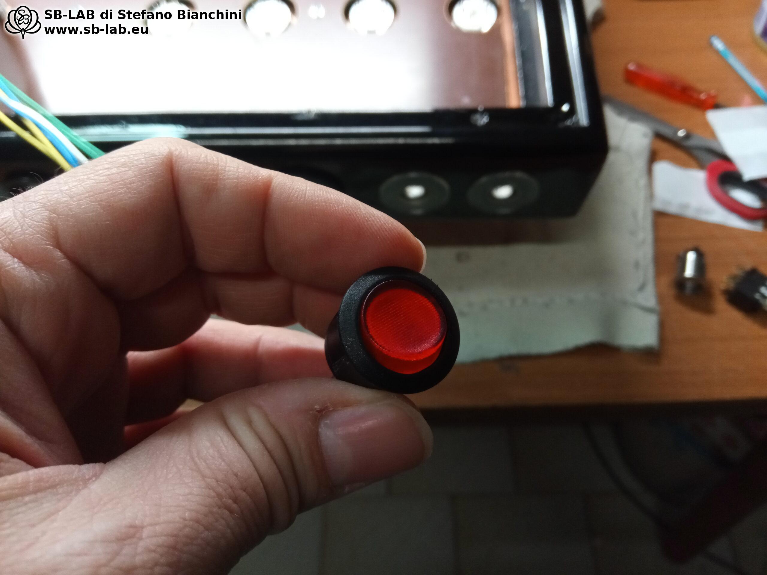
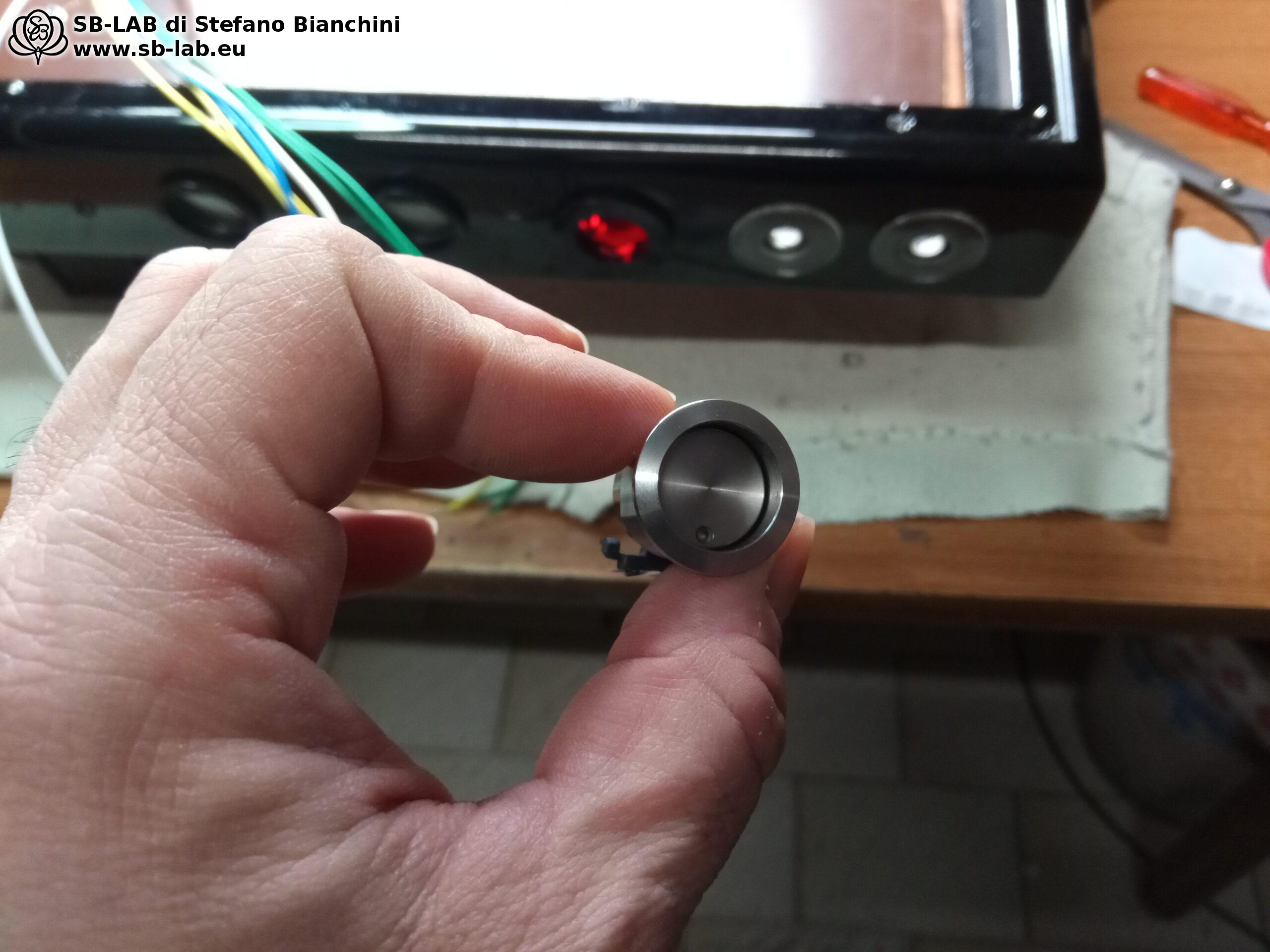
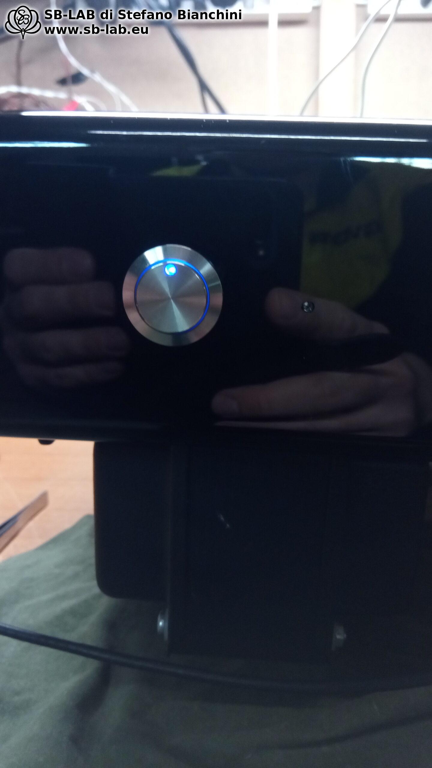
When assembling an object that requires so much effort and time, and therefore involves significant costs, it is crucial to use high-quality materials. In two photos I show the contrast between the plastic switch of the original unit and the stainless-steel anti-vandal switch I chose to install. The latter alone costs almost €60, but it’s a deliberate choice to ensure durability and long-term resistance, and the same applies to everything else.

In the next series of photos, I show the progress of the amplifier assembly. In the first image you can see the bare chassis of the amplifier, without transformers or any other components. This initial stage represents the starting point of the assembly process. In the second photo, the transformers have been mounted on the chassis, highlighting the base on which the rest of the circuit will be built.

As I proceed with the assembly, the following images show the addition of the mounting plate and the start of laying out the electronic components. We see capacitors, resistors and other essential parts being positioned precisely on the chassis. Each step illustrates the meticulous work and attention to detail required to complete the amplifier. The process continues until the amplifier takes shape, with all components soldered and installed correctly.

After the first power-up, the unit was not yet perfect in every detail. It was necessary to carry out a series of measurements and small tweaks, which involved changes to the circuit as I had initially built it. For example, I had to change the type of diodes and revise the very configuration of the high-voltage supply. I also reworked the supply for the current sink under the input phase splitters, making it quieter thanks to the addition of a small inductor I had on hand.

The tuning phase is crucial in a project like this. Even the smallest adjustments can make a big difference in the performance and reliability of the final device. This process requires patience and precision, but it is essential to ensure that the amplifier operates at its full potential. Each modification, however small, helps refine the circuit and optimize its overall operation.

Measurements
Maximum undistorted power: 25 Watts RMS per channel
Damping factor with zero feedback: DF 5
Damping factor with feedback engaged: DF 7
Total power consumption: 440 Watts
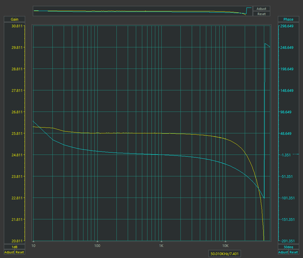
Bandwidth, zero feedback: 10 Hz / 20 kHz ?1 dB
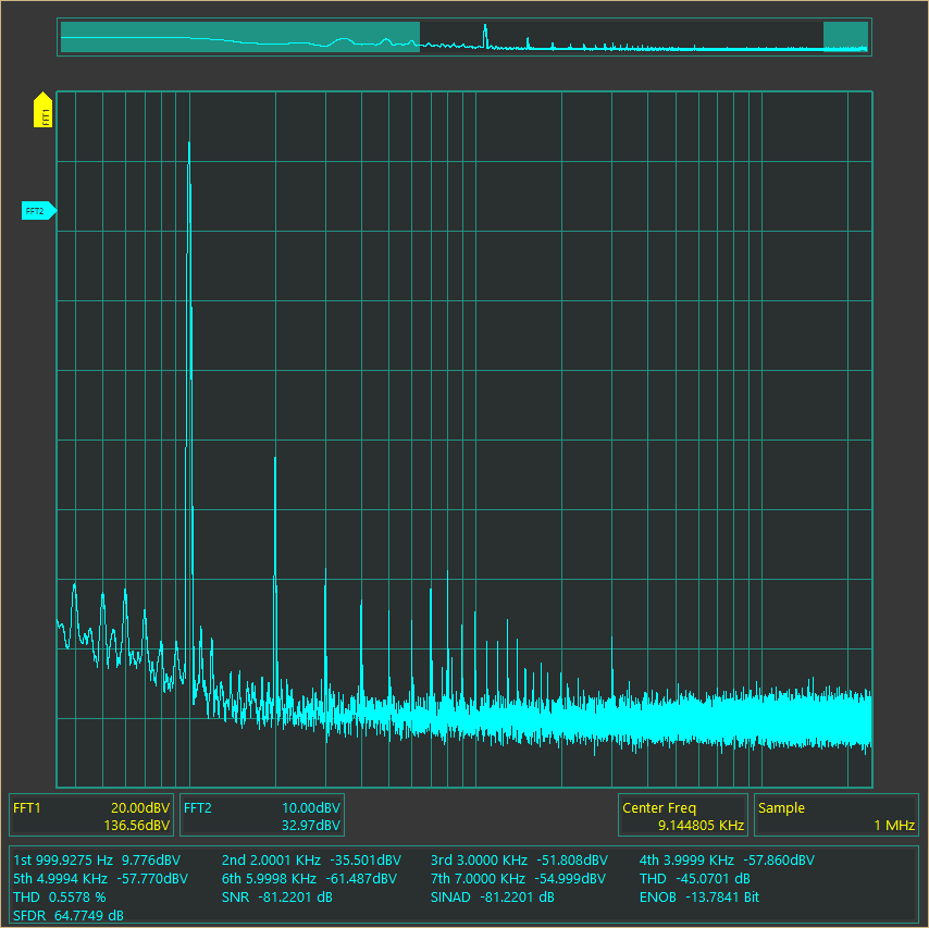
THD no NFB @ 1 watt: 0.55%
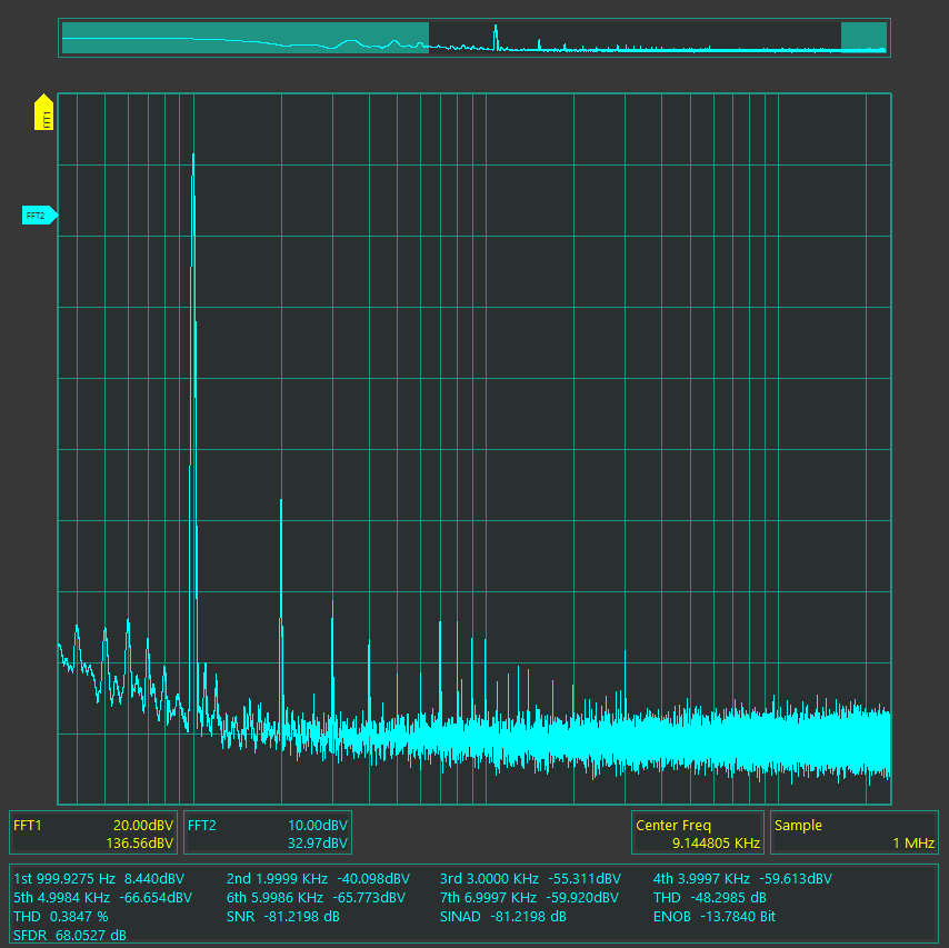
THD with NFB @ 1 watt: 0.38%

The bandwidth figure of the output transformers is not as extended as that of other transformers I have produced over the years. However, in this project I was constrained by the original chassis and had to use a core identical to the original. This forced me to apply a current density more than double my usual practice and to settle for a smaller core than I would have liked. Despite these limitations, the performance achieved is acceptable, also considering that the amount of feedback applied is really minimal.

The transformers I built are based on the design of the originals, which I unwound and to which I made some small changes. I kept the primary impedance, wire gauge and number of turns, but I changed the arrangement of the windings and the insulating sections. This compromise made it possible to achieve a satisfactory performance, given the conditions and the limitations imposed by the original chassis. Now let’s look at the classic plots…

Frequency response

THD without NFB

THD with NFB

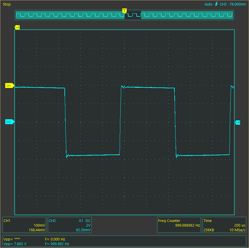
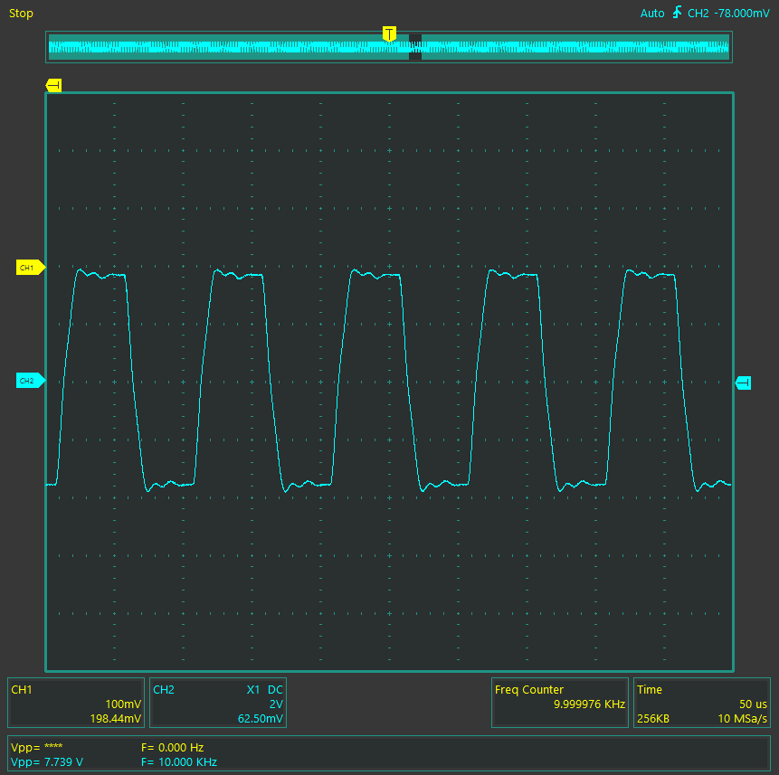
Square waves at 100 Hz – 1 kHz – 10 kHz

Presentation of the completed Anansi

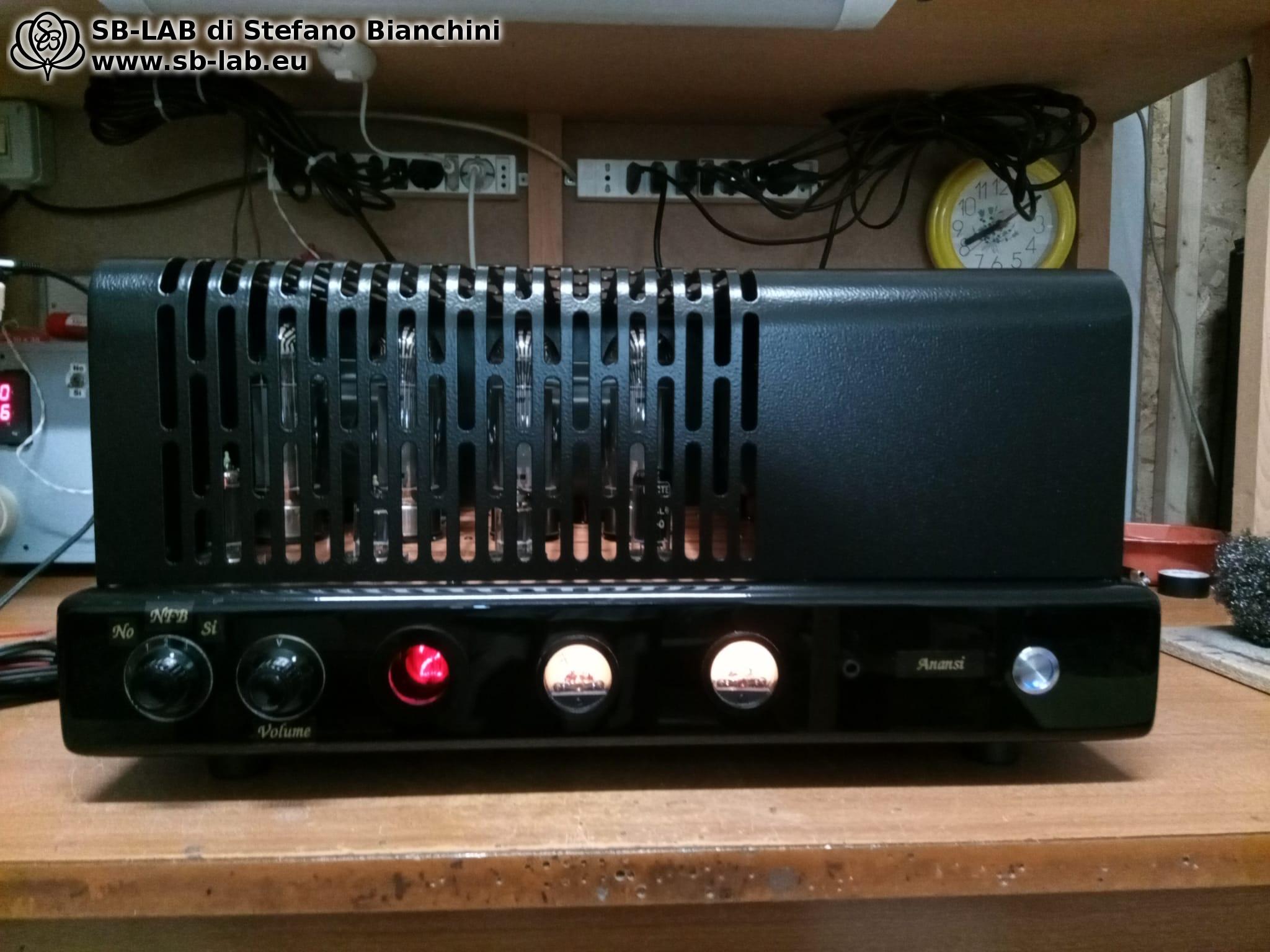
In the following photos, you can admire the Anansi amplifier fully assembled and ready for use. Those who read and see these photos might think that a project like this is quick to build, but in reality the process was extremely complex and detailed. From demolishing the original unit to SPICE design, from transformer design to salvaging all the components, from designing the various internal parts, to writing the software, fabricating the metalwork, assembly, testing and tuning, it took a full 82 hours of labor!

In this video, you can see Anansi in action and observe how it responds to the remote control. We start by showing the volume control: you’ll see how the volume level can be adjusted smoothly and precisely. Next, we demonstrate channel switching, with the Nixie clearly indicating the current channel. Finally, we show the automatic scanning function I implemented to prevent Nixie cathode poisoning.

Conclusion

The Anansi project represents a complex and rewarding journey, from dismantling a malfunctioning amplifier to creating a completely new and optimized device. Every phase of the process, from initial design to final tuning, required attention to detail, precision, and considerable commitment.

Anansi is not just an amplifier; it is a demonstration of craftsmanship, engineering, and dedication. Every component has been carefully chosen to ensure excellent performance and long-term durability. Advanced features, such as volume and channel control via remote and the prevention of Nixie cathode poisoning, add a touch of modernity and practicality to a classic design.

I hope this article and the related images and videos have provided a clear view of the work carried out and the attention to detail that led to the creation of Anansi. This project proves that, with dedication and skill, it is possible to turn an idea into a working, high-quality reality. Thank you for following this journey and for your interest in my work.

Continue reading...

Leave a Reply

This site uses Akismet to reduce spam. Learn how your comment data is processed.