Granny 27 – DAC Preamplifier with UY227 Tubes

In May 1927 one of the very first indirectly heated tubes was introduced, initially called YU227 and later simply 27. It is the cathode version of the 26, which was directly heated. It was conceived to serve as a detector and audio preamplifier and was produced to reduce filament-induced hum compared with the 26. It can readily be used to drive a 45 or other small output tubes of the era. The 27 is the progenitor of a long line of small signal triodes that ultimately led to the 6SN7. Availability of this tube is still very good, including the “ST/balloon” shape.
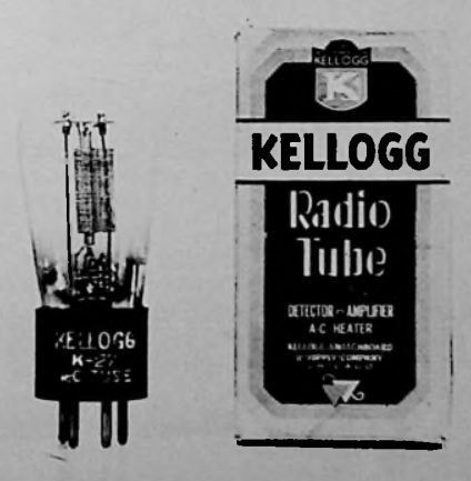
Years ago, when I began the first experiments that later led to Nibiru, I built what I called a “26 audio processor,” a sort of unity-gain preamplifier that wasn’t a buffer, based on the 26.
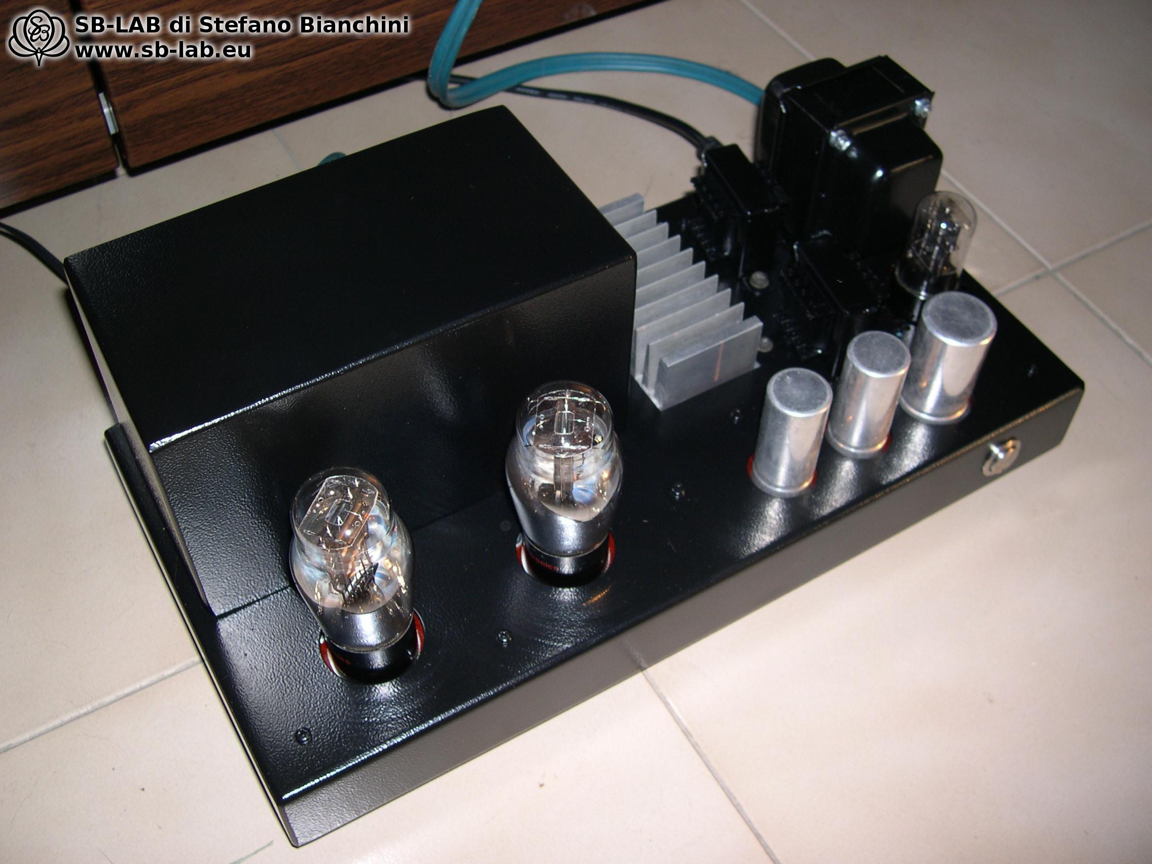
The goal was to add a bit more three-dimensionality and “tube sound” to a digital audio source that already had enough output to drive a power amp directly. Using what’s called a buffer (more correctly a cathode follower) — i.e., sending a signal through a tube with 100% intrinsic feedback, operating at unity gain — seemed pointless to me. I had already sensed that the key lay in reactive elements, so I wound a pair of line transformers with about 150 H primary inductance and a 7:1 turns ratio. Since the mu of the 26 is 7, a zero-feedback circuit would let the 26 amplify and the transformer would bring the signal back down to roughly the original amplitude. The circuit worked, but in addition to misjudging capacitor usage, I underestimated the issue posed by the 26 filaments, which must be powered by a stabilized 1.5 V DC at 1 A — otherwise, hum. I tried to size the supply and regulator properly; it worked, but the heatsink needed to cool the filament regulators had to be much larger than the one I used… after an hour you could fry eggs on it! On top of that, the sonic effect was almost negligible — it was hard to tell whether the circuit was in the chain or not — so I scrapped it to salvage the parts.

At the beginning of February this year (2020) I started thinking again about that trashed project, also recalling the excellent experience with the USB Mini DAC. I decided to merge the two ideas using a more advanced DAC board and found on eBay, for about €30, a small DAC based on the Sabre 9023P — asynchronous USB, 24-bit/96 kHz.
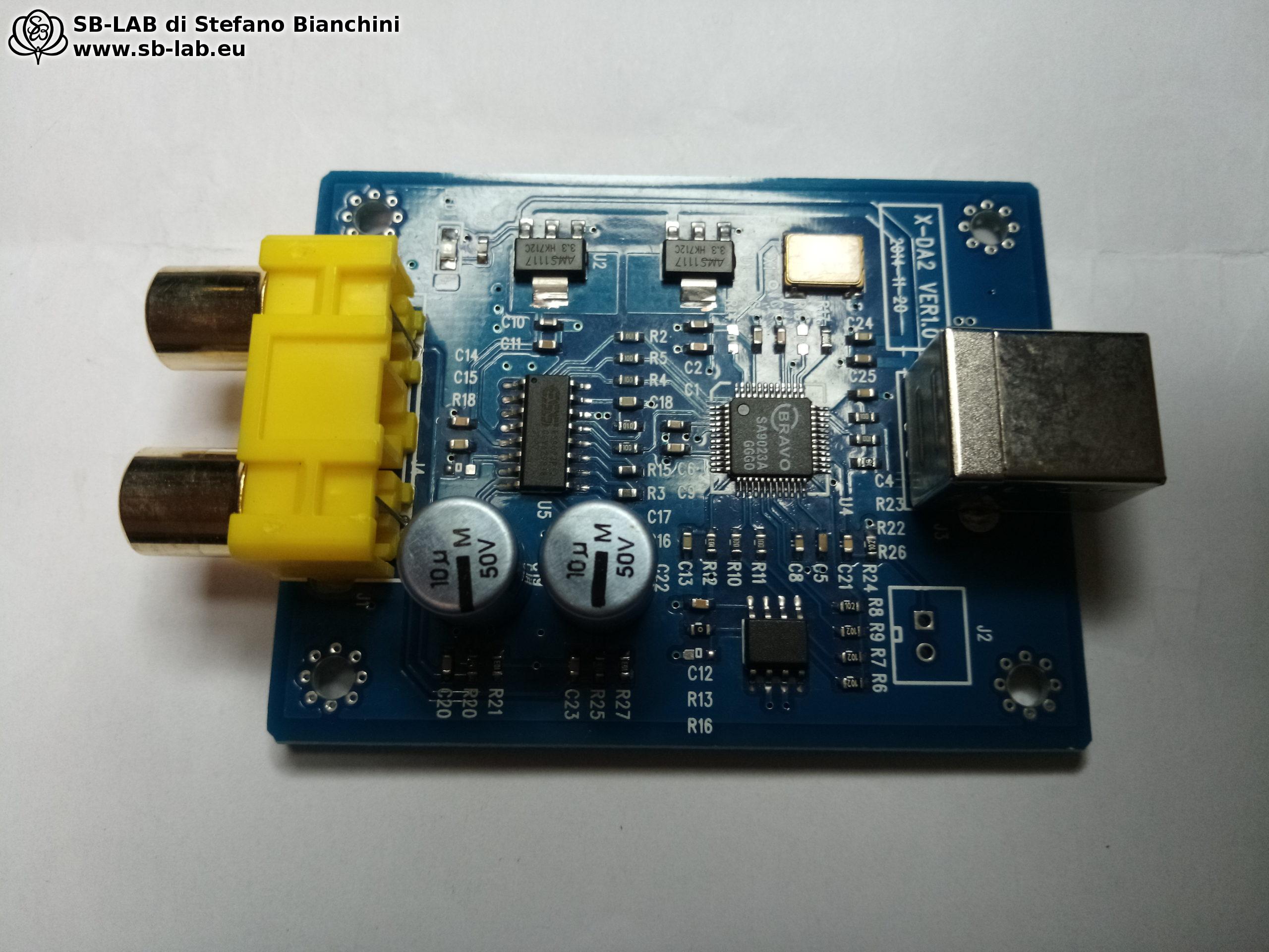
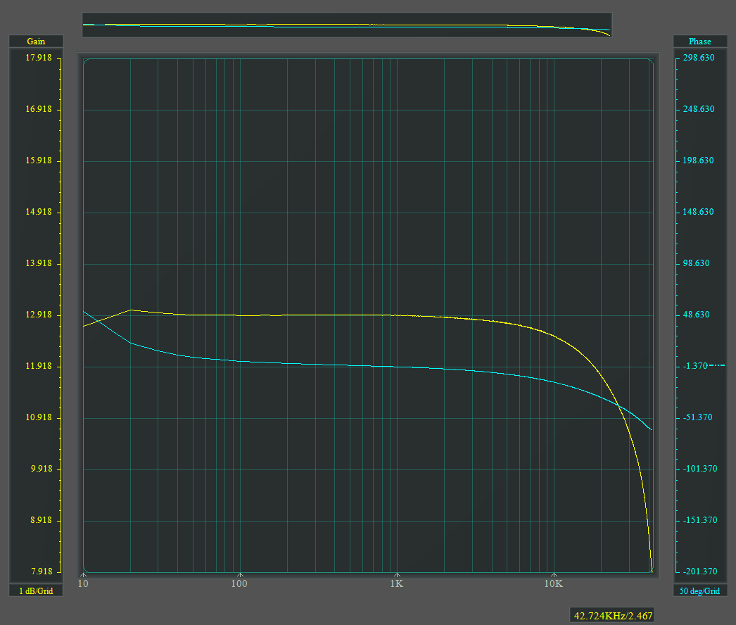
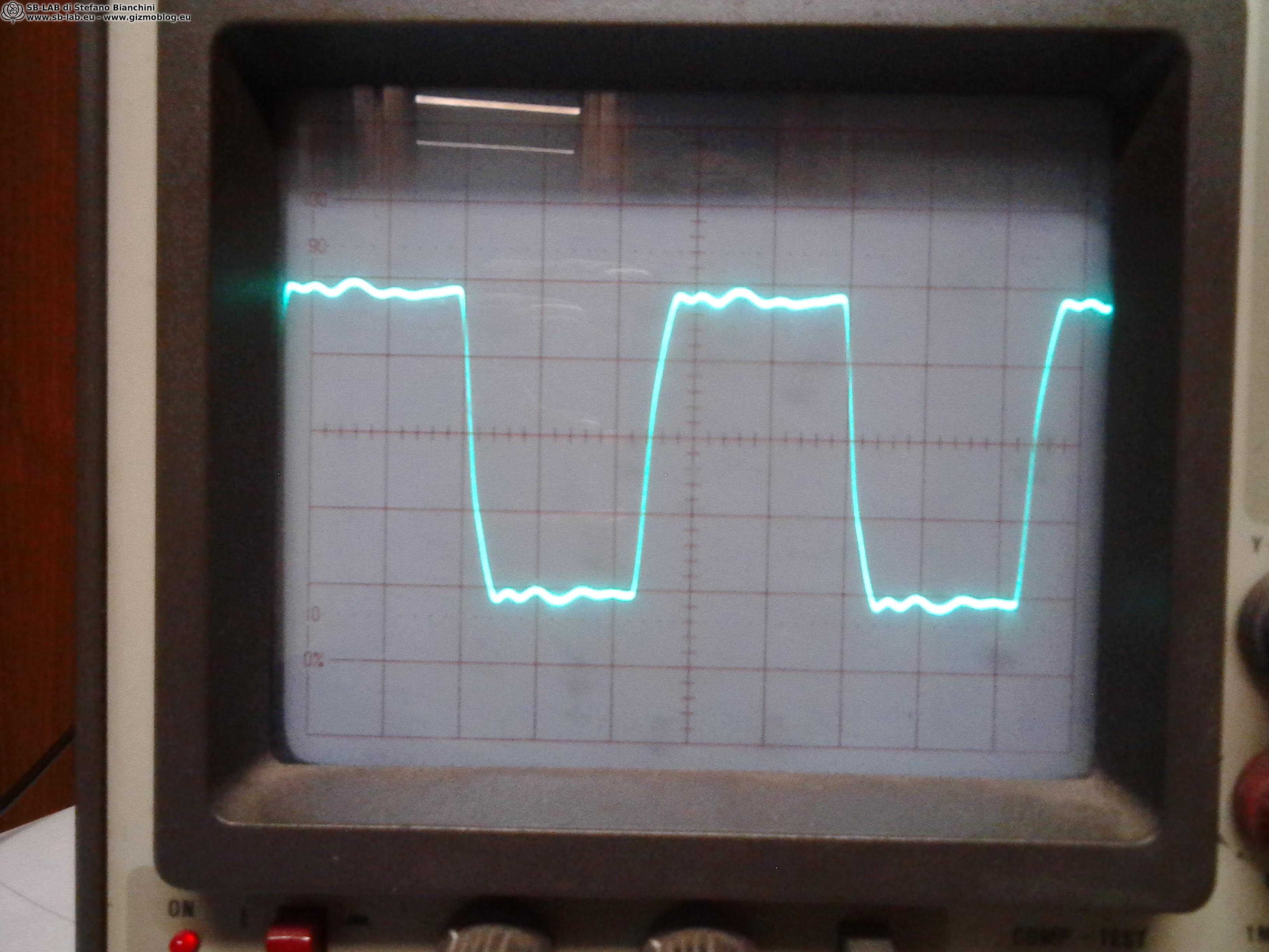
When it arrived I tested it and, even by itself, it sounded very good. Lockdown had begun and work was slow due to restrictions; since I had lots of parts on hand, I decided to start a new project based this time on the 27. I dug out the two line transformers I’d made for the 26 and built a quick lash-up on the bench. The 27 has a mu of 9, while the transformer divided by 7 — perfect to apply what I learned from Nibiru, add a hair of local NFB, and get good three-dimensionality. By ear it seemed to work well. I liked the bench build even though it wasn’t perfect; the measurements showed the following frequency response:
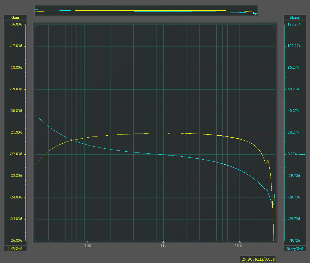
It wasn’t so much the –1.5 dB at 10 Hz, but rather the low-frequency phase response that wasn’t ideal, while –1 dB at 25 kHz on the top end was acceptable. Also, my line transformers were big and heavy because they were made with standard EI oriented-grain laminations.
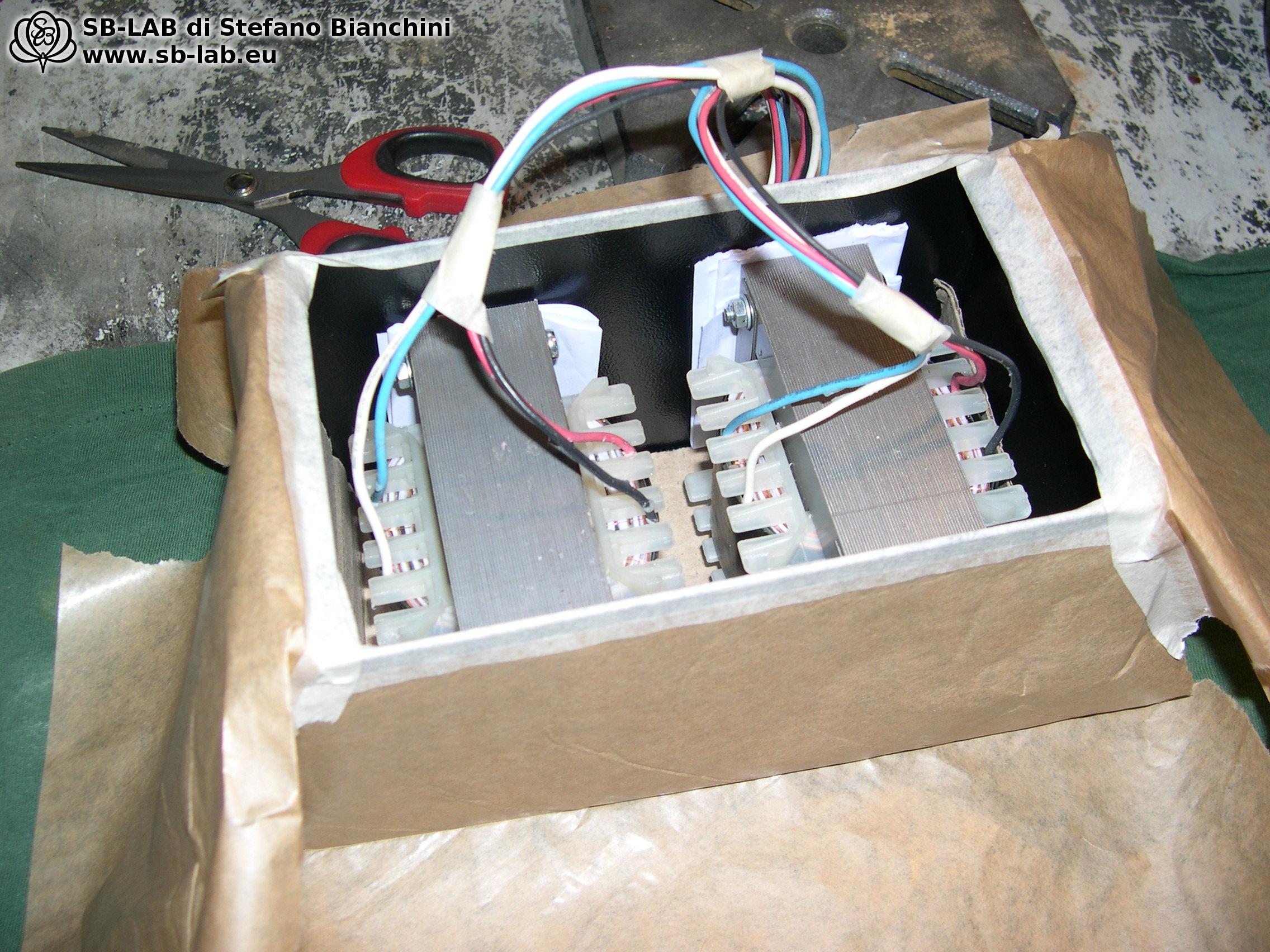
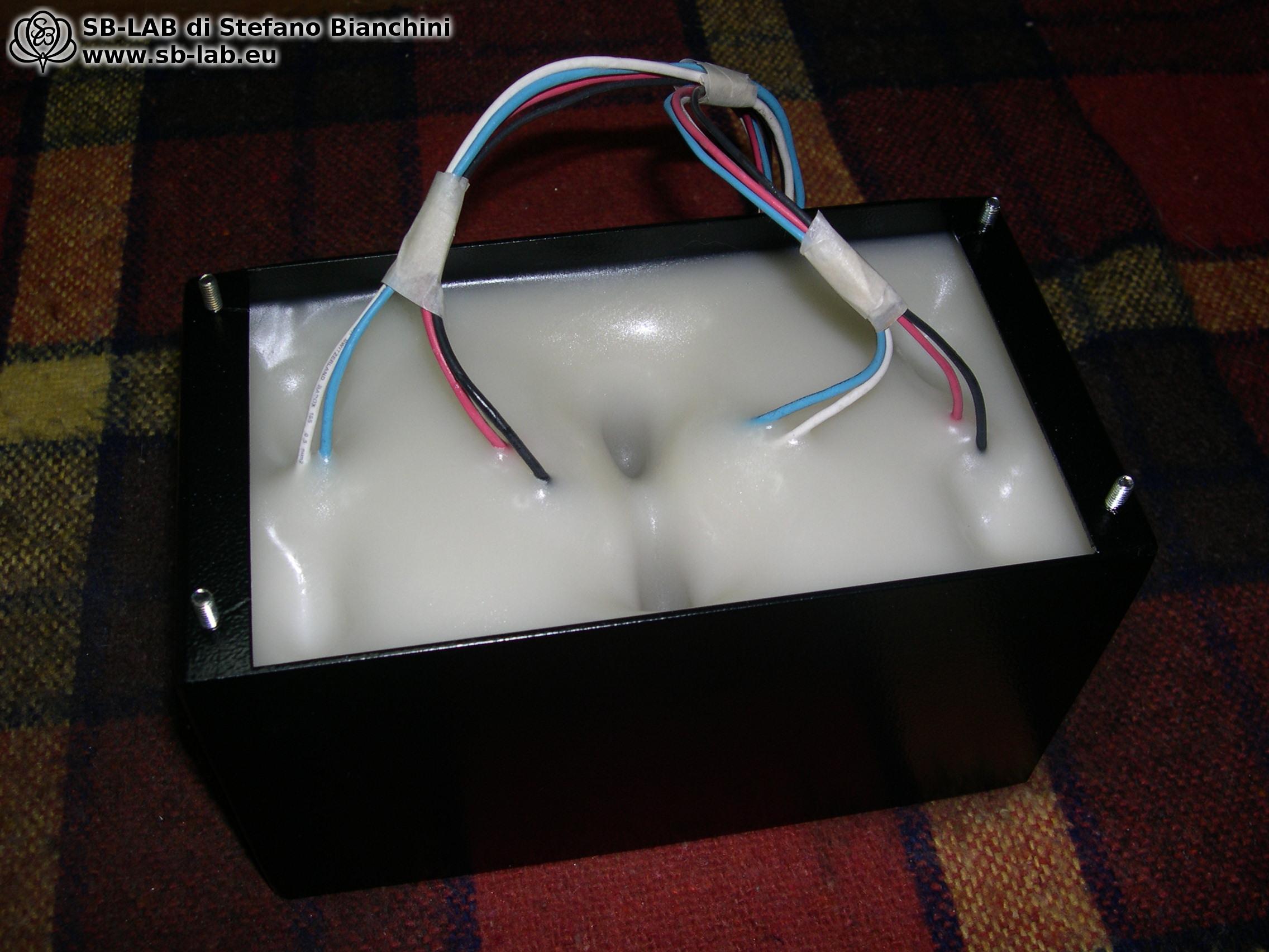
Since I wanted to build something TOP and didn’t feel like hunting down C-cores (one area where they truly have an advantage over EI for small-signal transformers), not knowing whether I’d find good-quality ones, I — perhaps forgetting the reasons I started winding transformers years ago — took a leap of faith and bought a pair of line transformers from a very famous manufacturer. It was an older model still in production, the only one with roughly a 7:1 ratio, thus the only one from that maker I could use. The datasheet promised a flat response from 10 Hz to 40 kHz with 5 mA DC in single-ended use, so I forked out €300 and waited for the package. When they arrived I put them on the bench — and the huge disappointment arrived… 👿
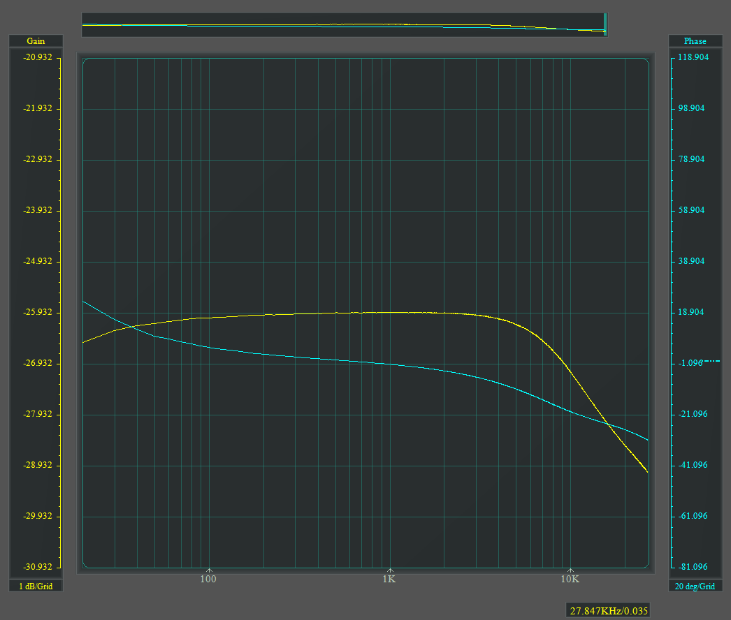
I measured –1 dB at 9 kHz — unspeakably poor. Maybe I was doing something wrong. I consulted the same manufacturer via the reseller, ran test after test with different tubes and wiring schemes, but nothing. In the best case I got –1 dB at 20 kHz with a 14:1 ratio by wiring the secondaries in a way not even covered in the datasheet. I spent three days testing — one of them until about 2 a.m. — driven by the frustration of having thrown away €300 and dragged back to the anger from years ago when I bought gear that didn’t perform as claimed because “buyers can’t measure and go by ear”… Too bad I had no intention of listening to a chopped-off top end like a little Geloso PA amp!

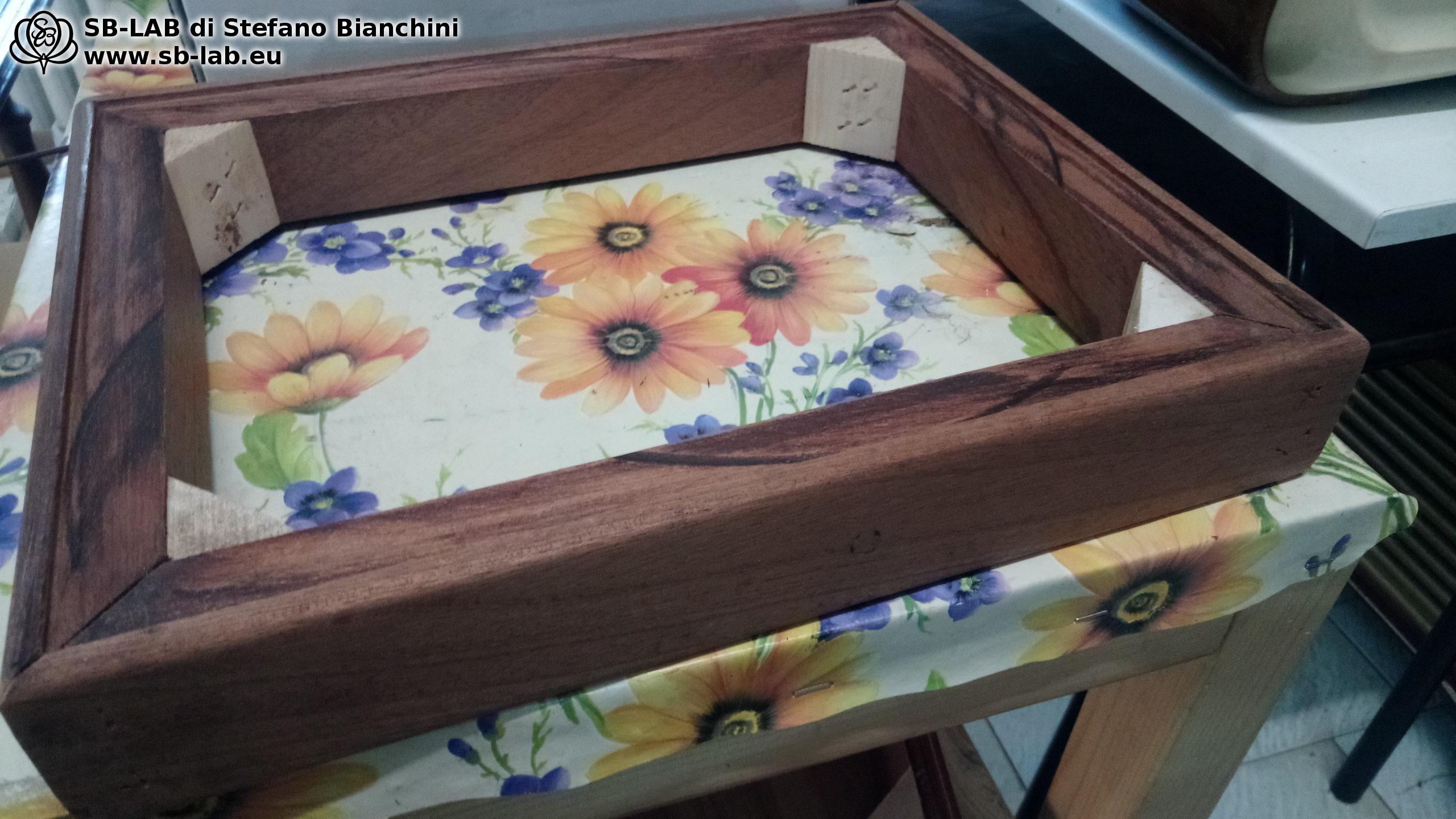
I sent the package back and to this day I’m waiting for a response about the fault, a replacement, or a refund. With that behind me, I pushed forward using my original transformers. I had a wooden chassis and couldn’t get another — we were in the middle of a pandemic, everything was closed, nobody was working. Something inside me feared the power transformer might be too close, but the line transformers were rotated the other way and shielded by a steel box… The urge to build won out…
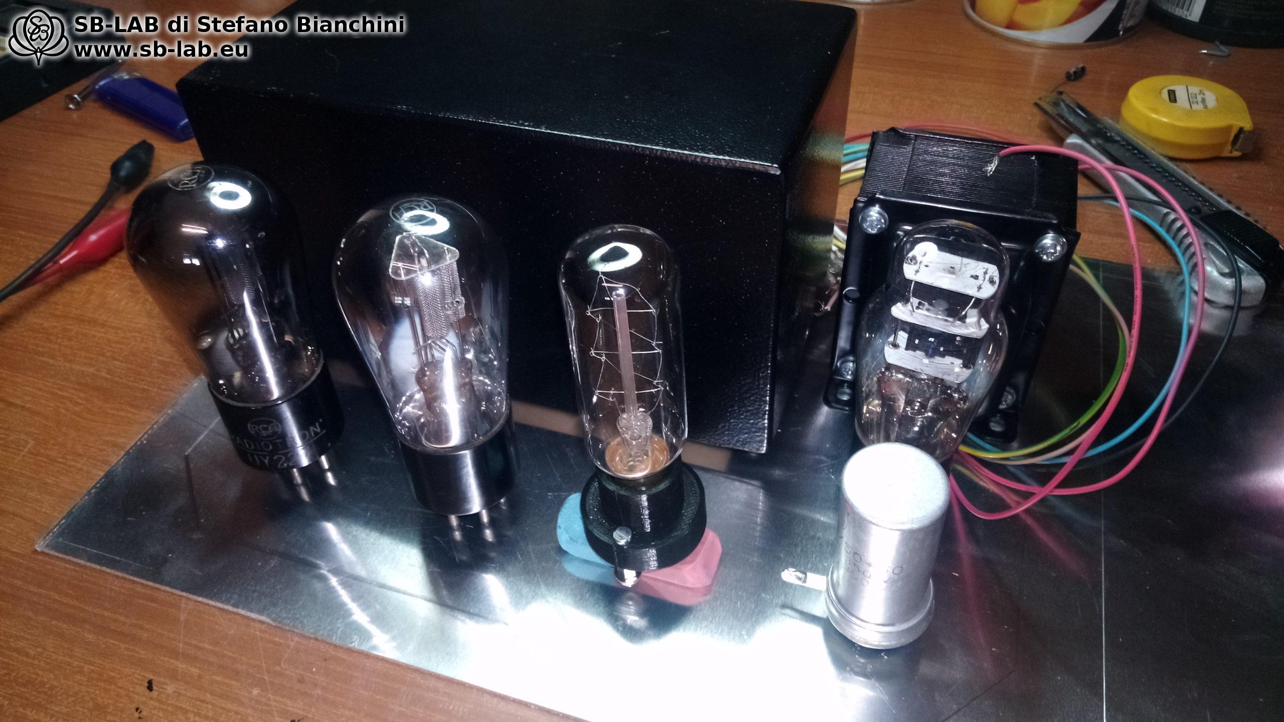
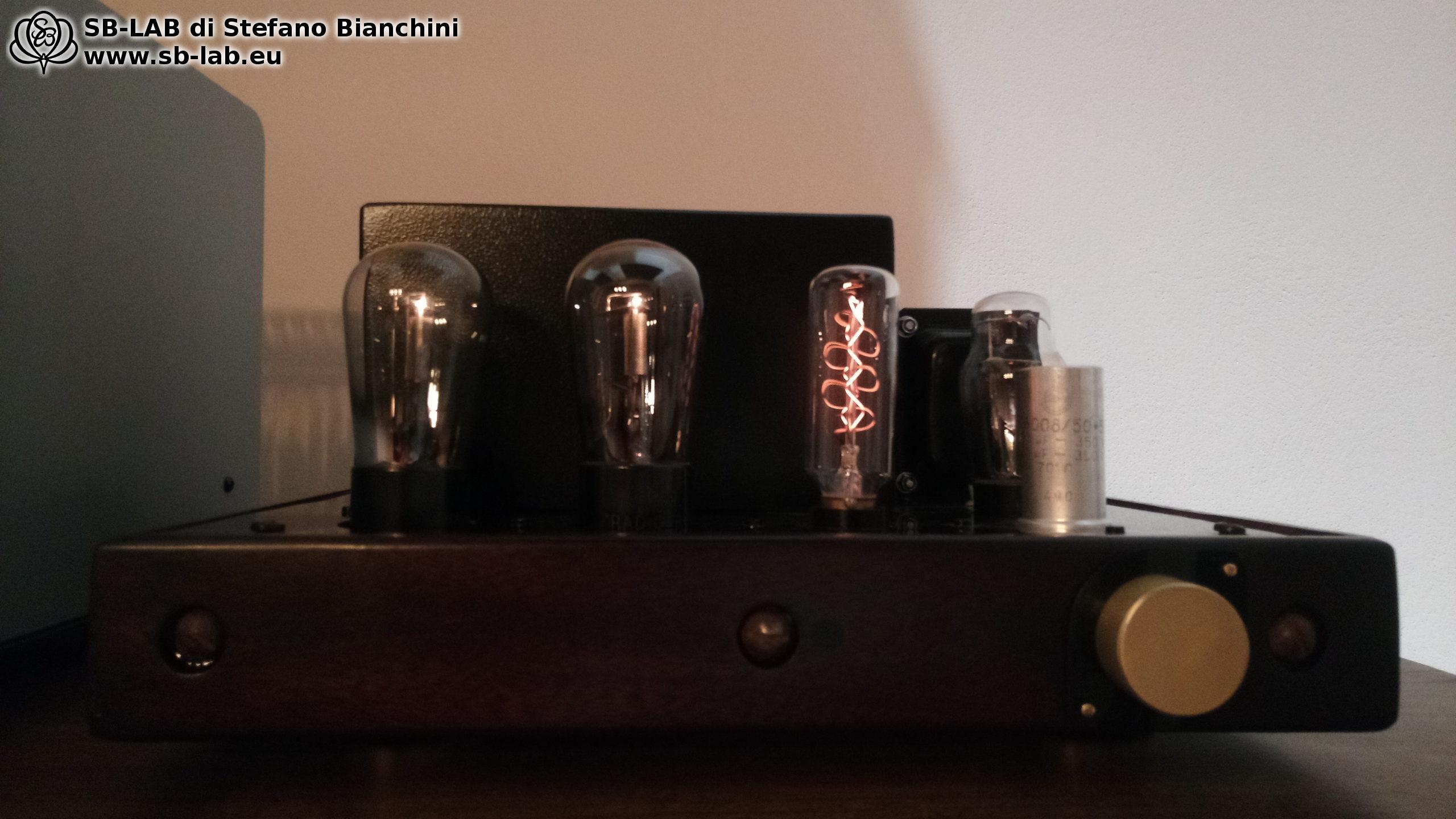
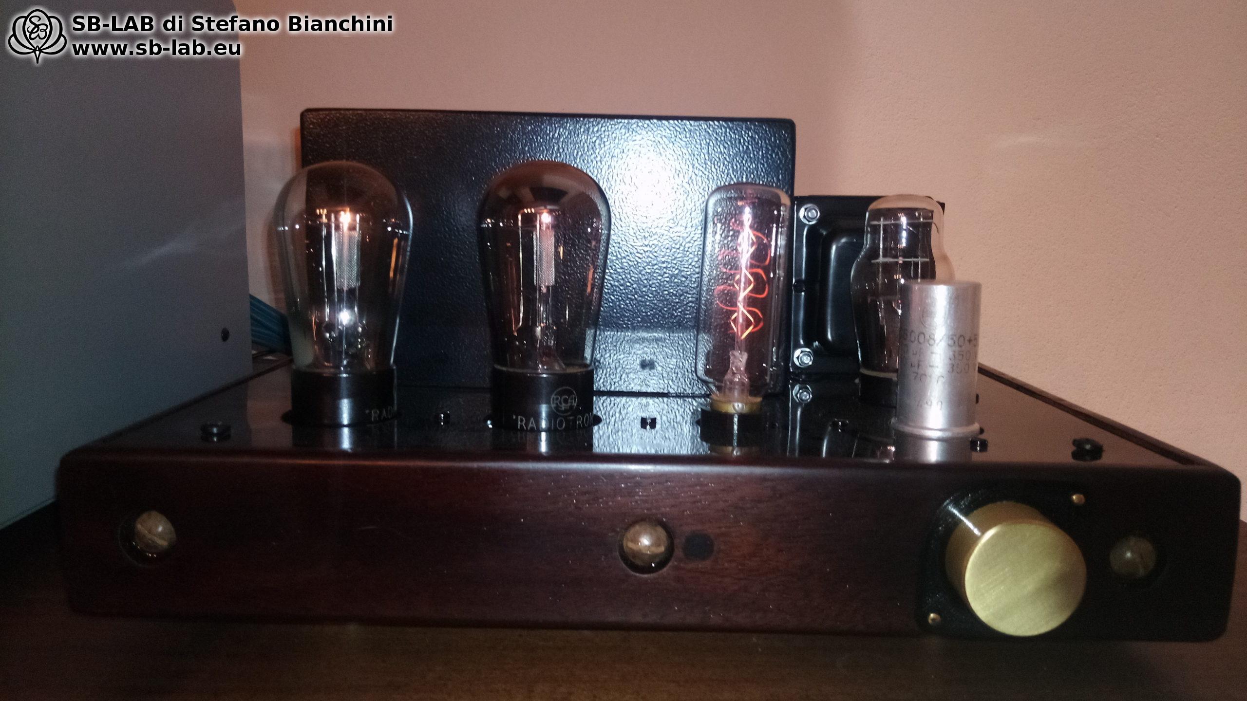
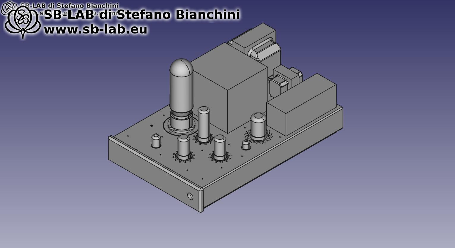
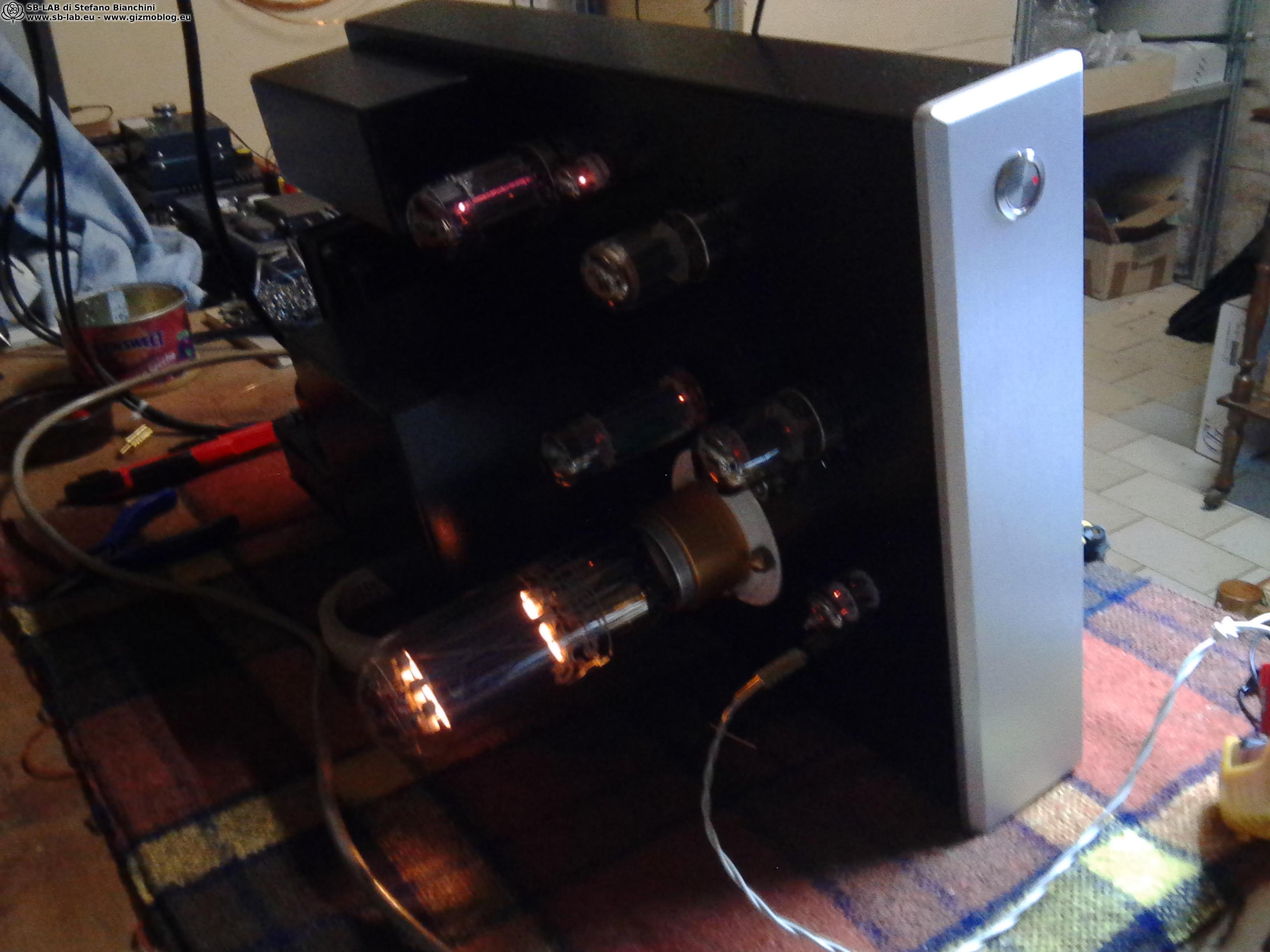
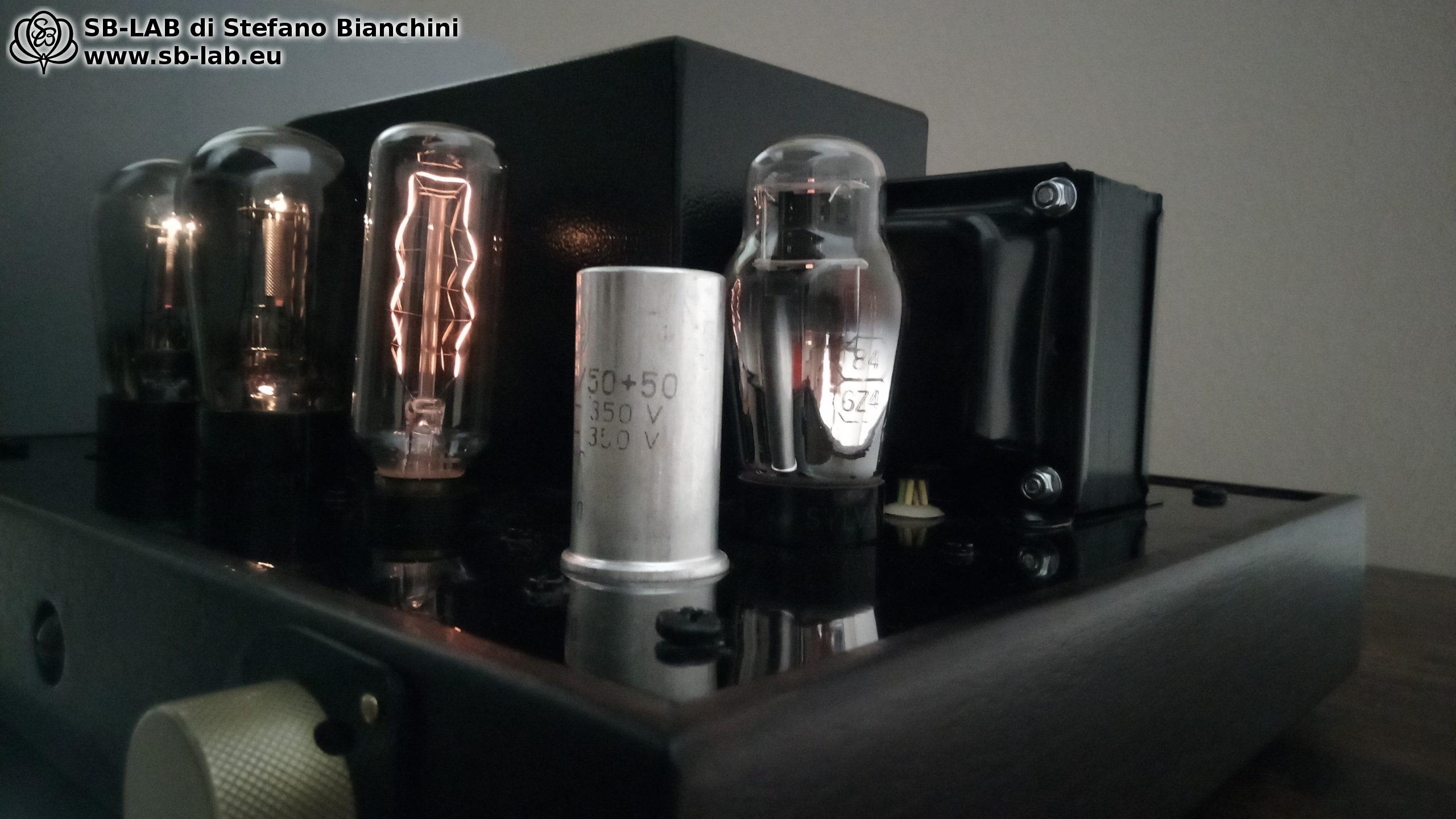
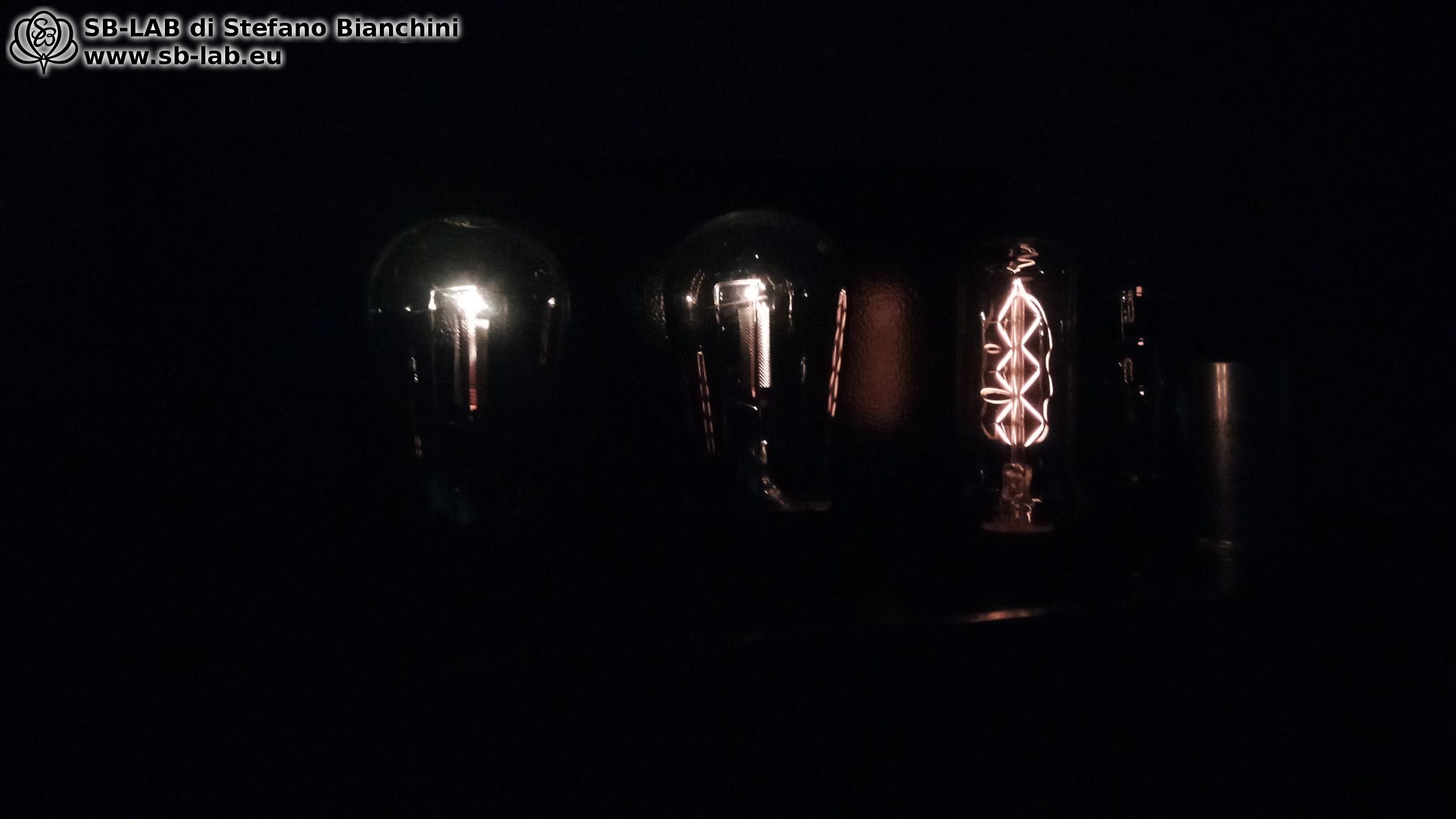
The third glass from the left isn’t a tube — it’s an old light bulb rated for 140 V and 15 W, probably the turntable-bay light from some radio. Powered at low voltage (20/30 V) it looked beautiful. I was going for an “industrial” aesthetic I really like, and it fit the look — but I also wanted it to serve a purpose in the circuit. I wanted fixed-bias on the 27s but didn’t want coupling capacitors in the audio path between the DAC and the tube. So I created a shunt regulator to generate 15 V to lift the cathodes of the 27s. I calculated the transformer and regulator to use this lamp as the shunt resistor. It has no “sonic” or technical purpose — a 250 ohm 3 W resistor would have done the same job — but this way I hit two birds with one stone. The lamp will also last a long time, being run at only about 3 W (and I have spares anyway).
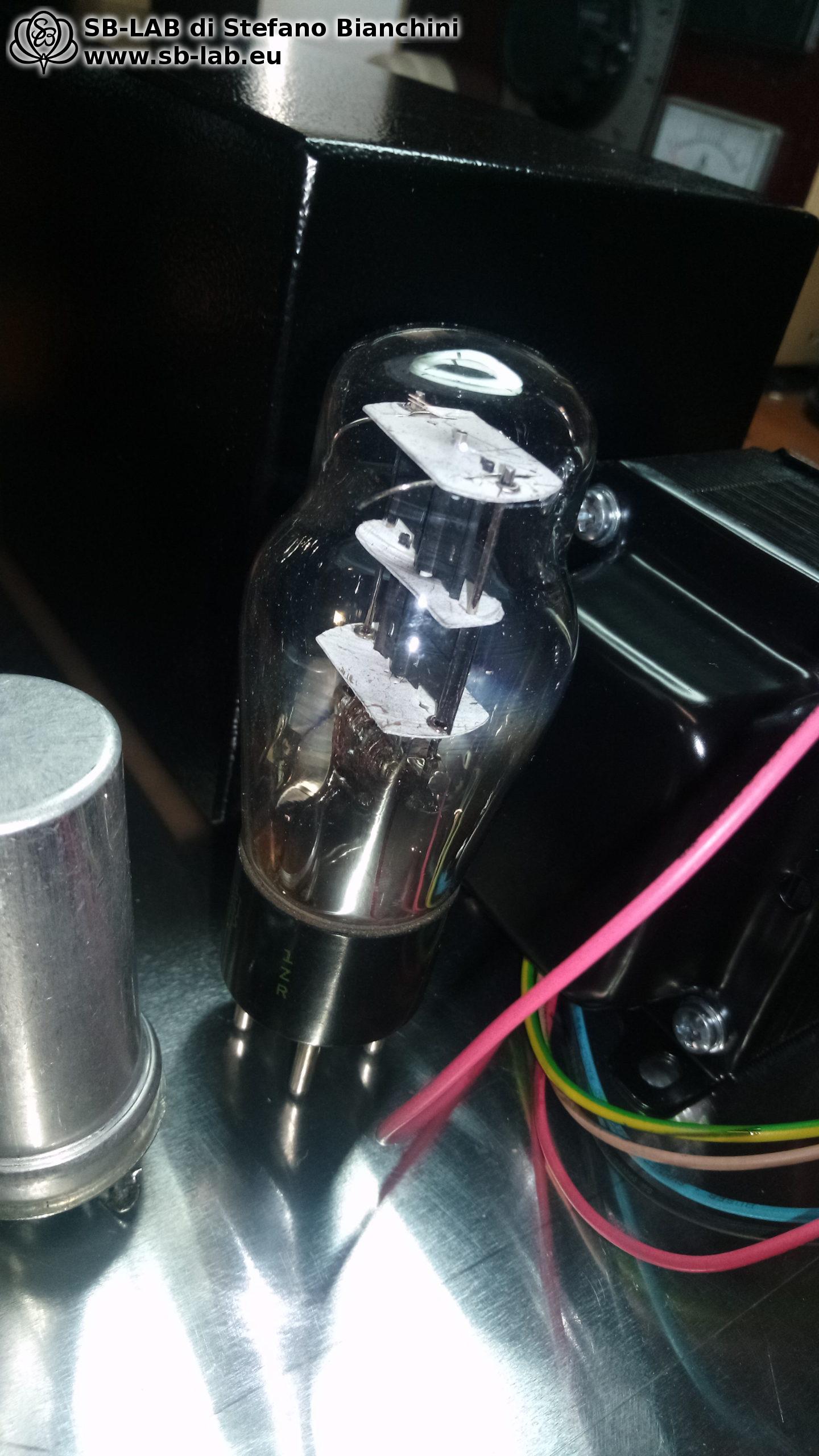
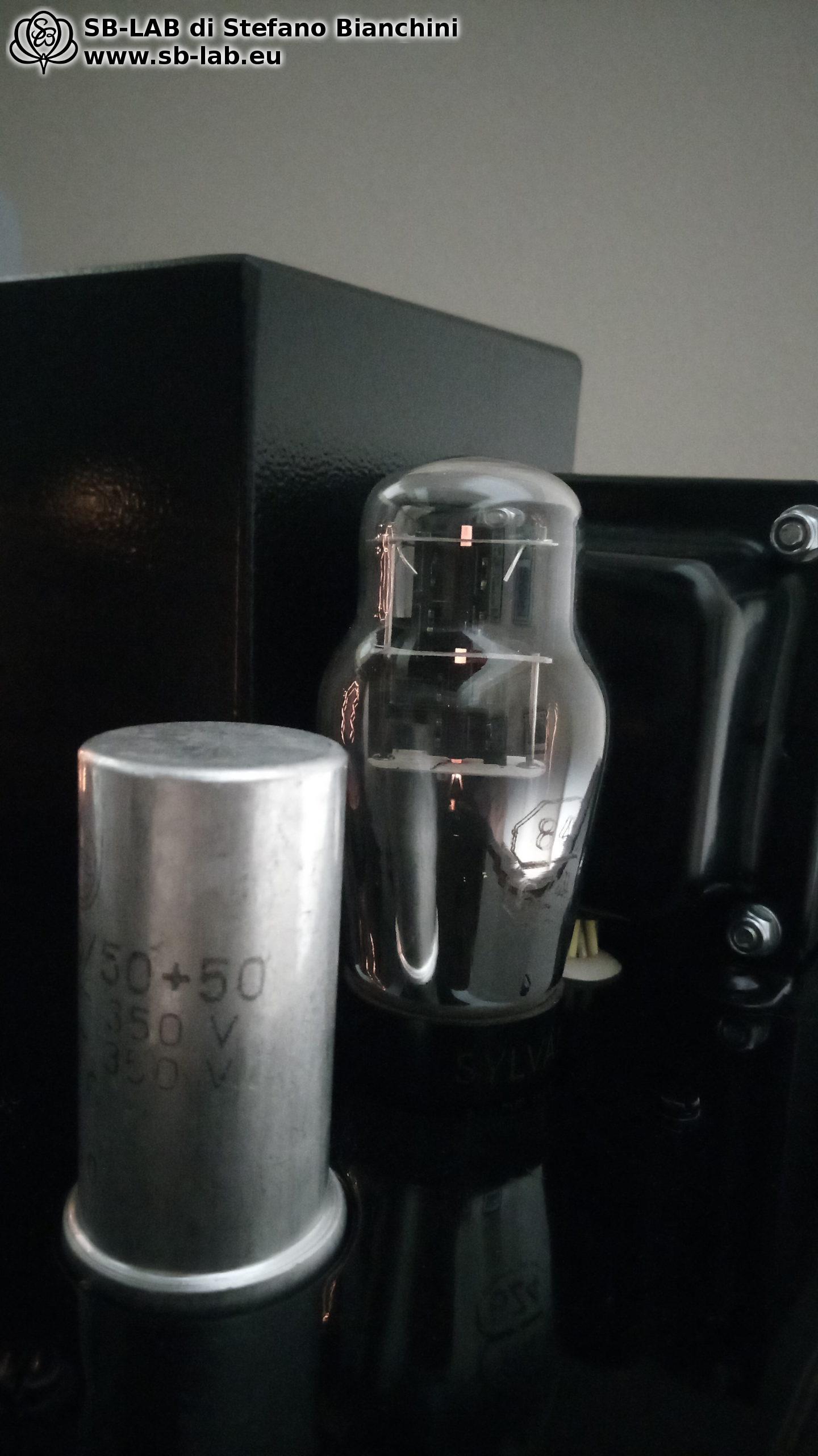
In the power supply I used an 84 / 6Z4, a small rectifier from the same era as the UY227 — although it has a dome bulb (the pear-shaped “98” version is unfortunately unobtainable), while the 84 is fairly common. It can supply 60 mA, more than enough for the two 27s, which draw 5 mA each. The 84 is the forerunner of the 6X5G/GT; electrically they are the same, differing only in base type.

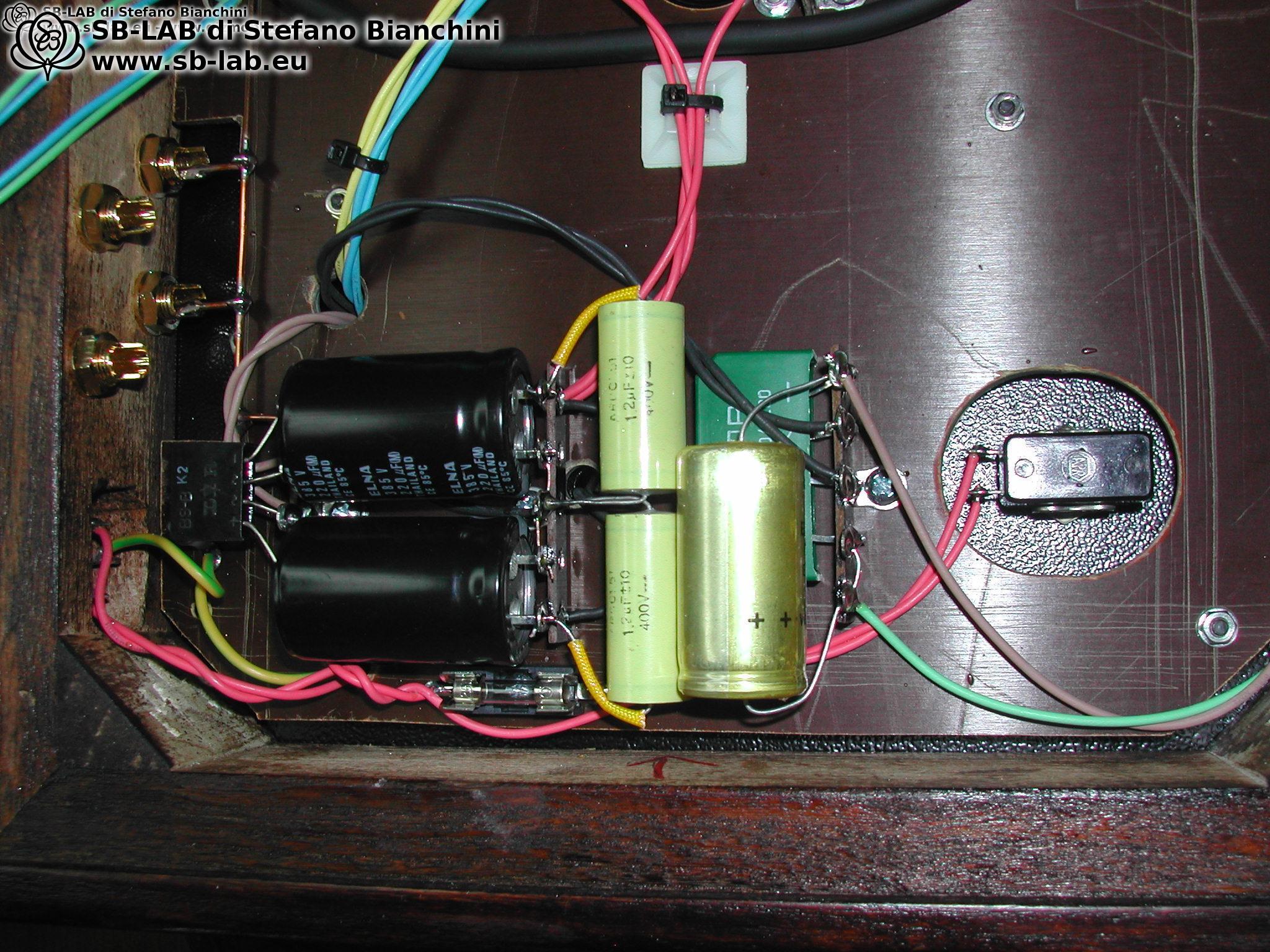
The rectifier is followed by a CLC cell formed by a NOS Philips dual electrolytic 50+50 µF and a 15S55 20 H choke. Why the old capacitor? Simple: when measured, its ESR and dissipation factor are one-tenth those of typical industrial caps with comparable values. Surely there are “audio-grade” caps you can buy for around €20, but I have a sack of these new; I’ve used tons of them in radio restorations and I know they work perfectly, are reliable with excellent electrical characteristics, and they also match the aesthetic I wanted.

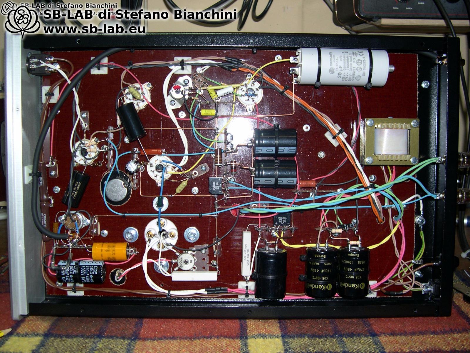
After the electrolytic there’s an additional RC cell with a 20 ohm resistor and a 2 µF Siemens paper-in-oil capacitor — a technique used by the great Mariani to decouple the electrolytic at mid/high frequencies and let the paper-in-oil “speak.” In the photo below you can see the little silver brick.
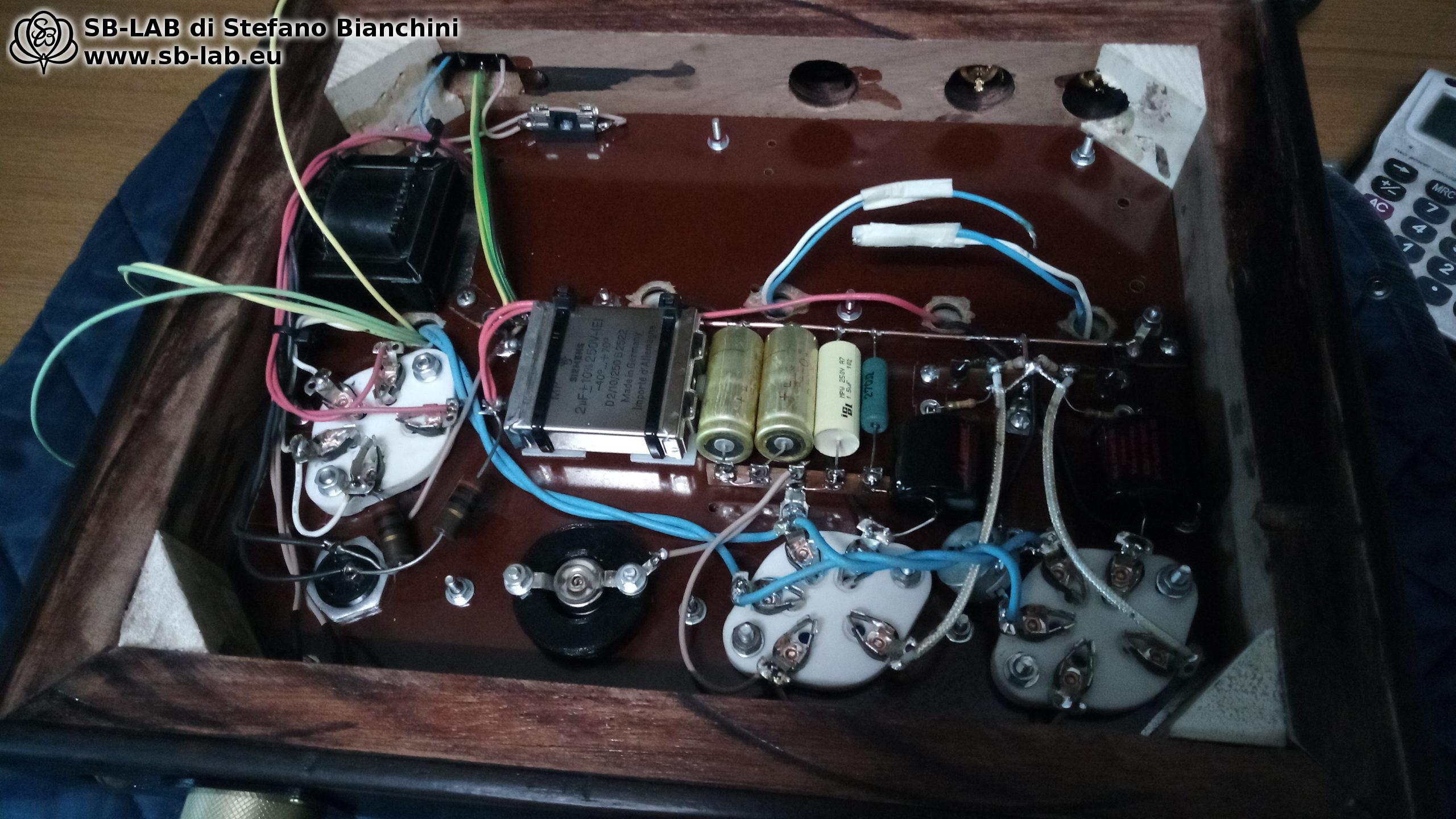
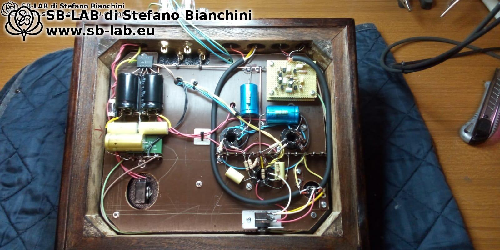
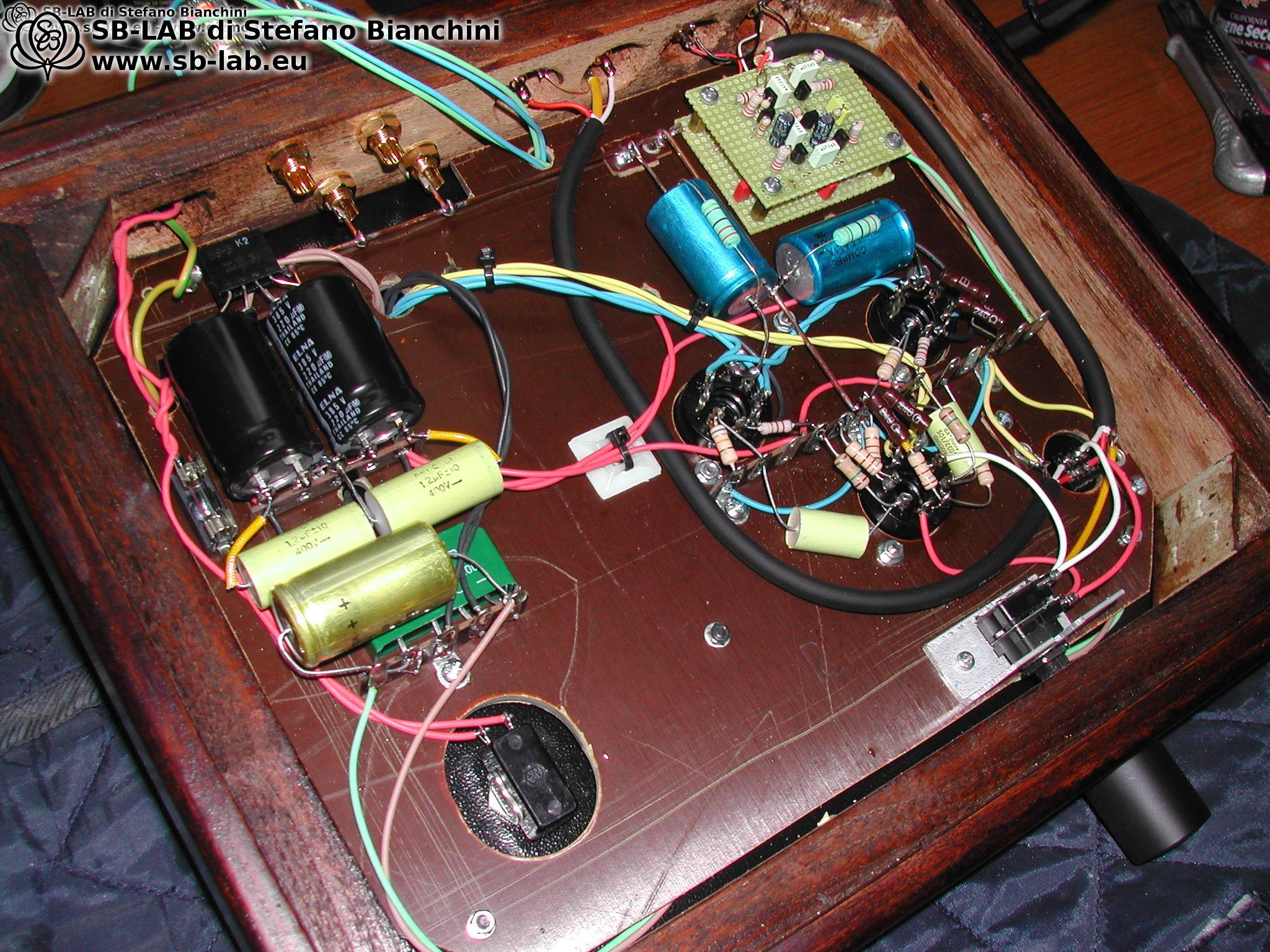
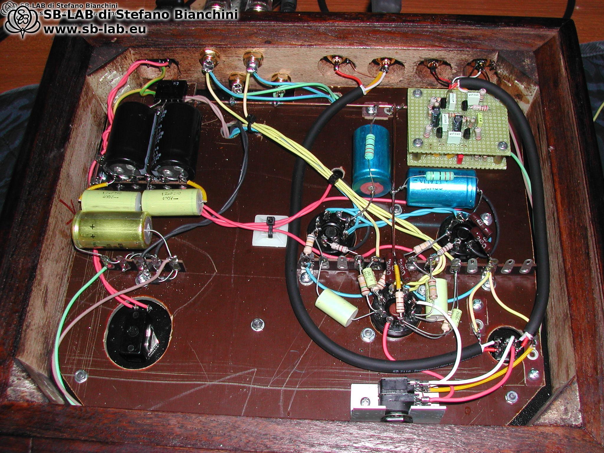
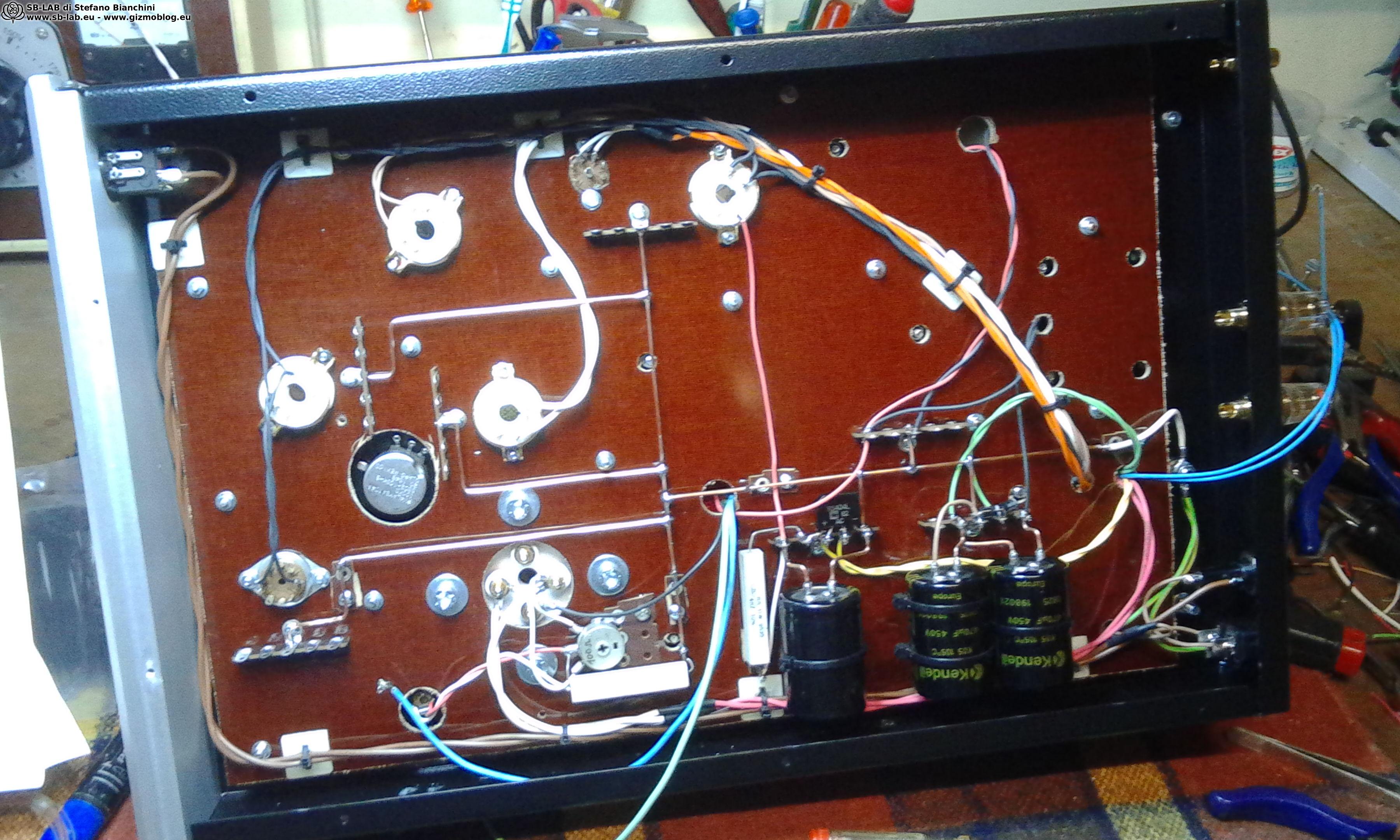
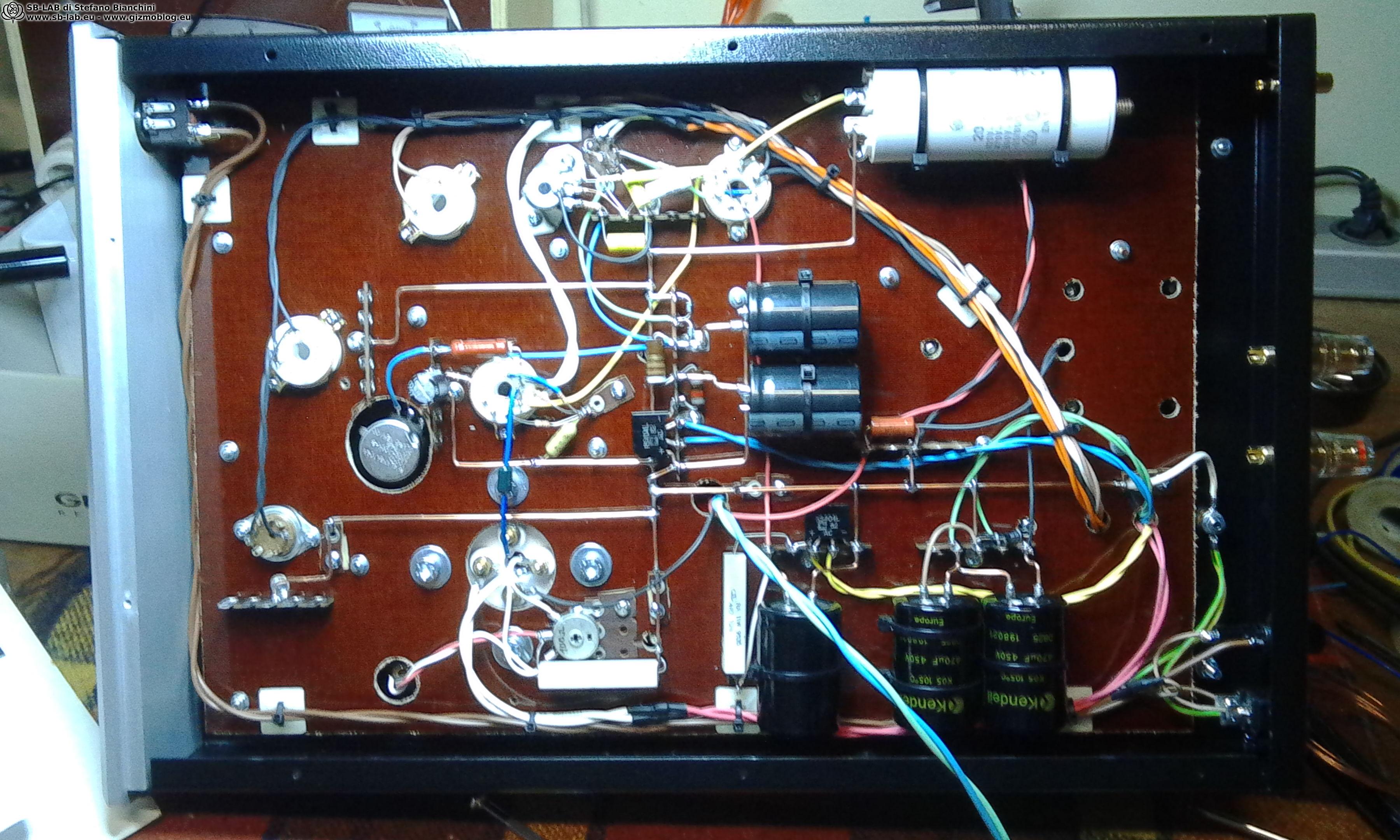
Assembled and finished…
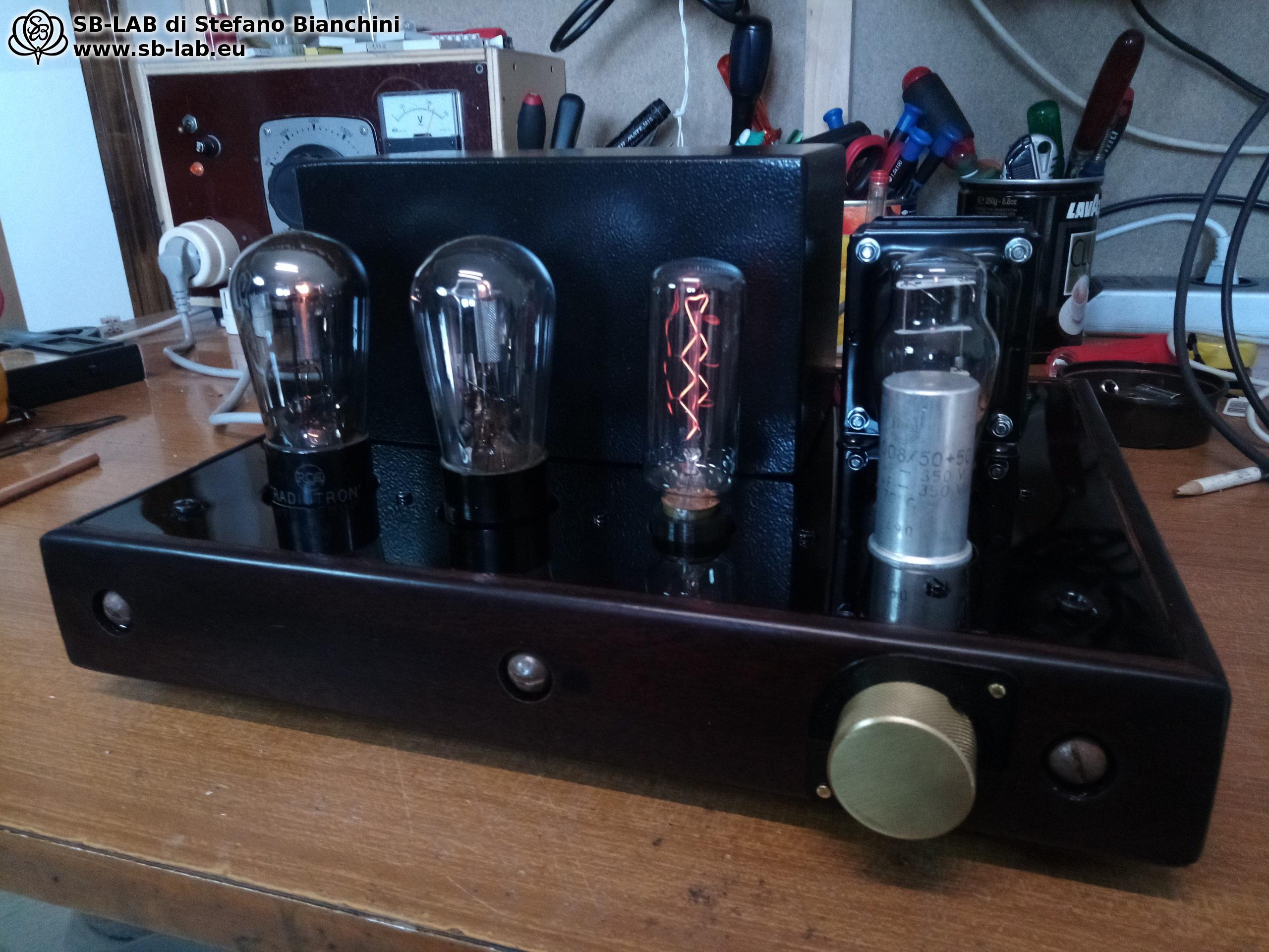
The knob isn’t a volume control — it’s just the power switch. Unfortunately, on first power-up the thing I feared happened: the power transformer induced a slight hum audible from the speakers, very low but still irritating. With music playing you didn’t notice it, but it bothered me. I should have used a wider chassis to space the power transformer farther away, but I couldn’t get one during lockdown. If the small commercial line transformers had worked, I probably wouldn’t have had any problem — I would have mounted them on the left, far from the power transformer. I held out a few days; the Nibiru effect was there, but I couldn’t stand that background HUMM anymore, so in the end I decided to disconnect the two line transformers, use a CCS as the plate load, and take the signal directly from the plate — even if that meant no longer having unity gain; I could just turn down the power amp volume…
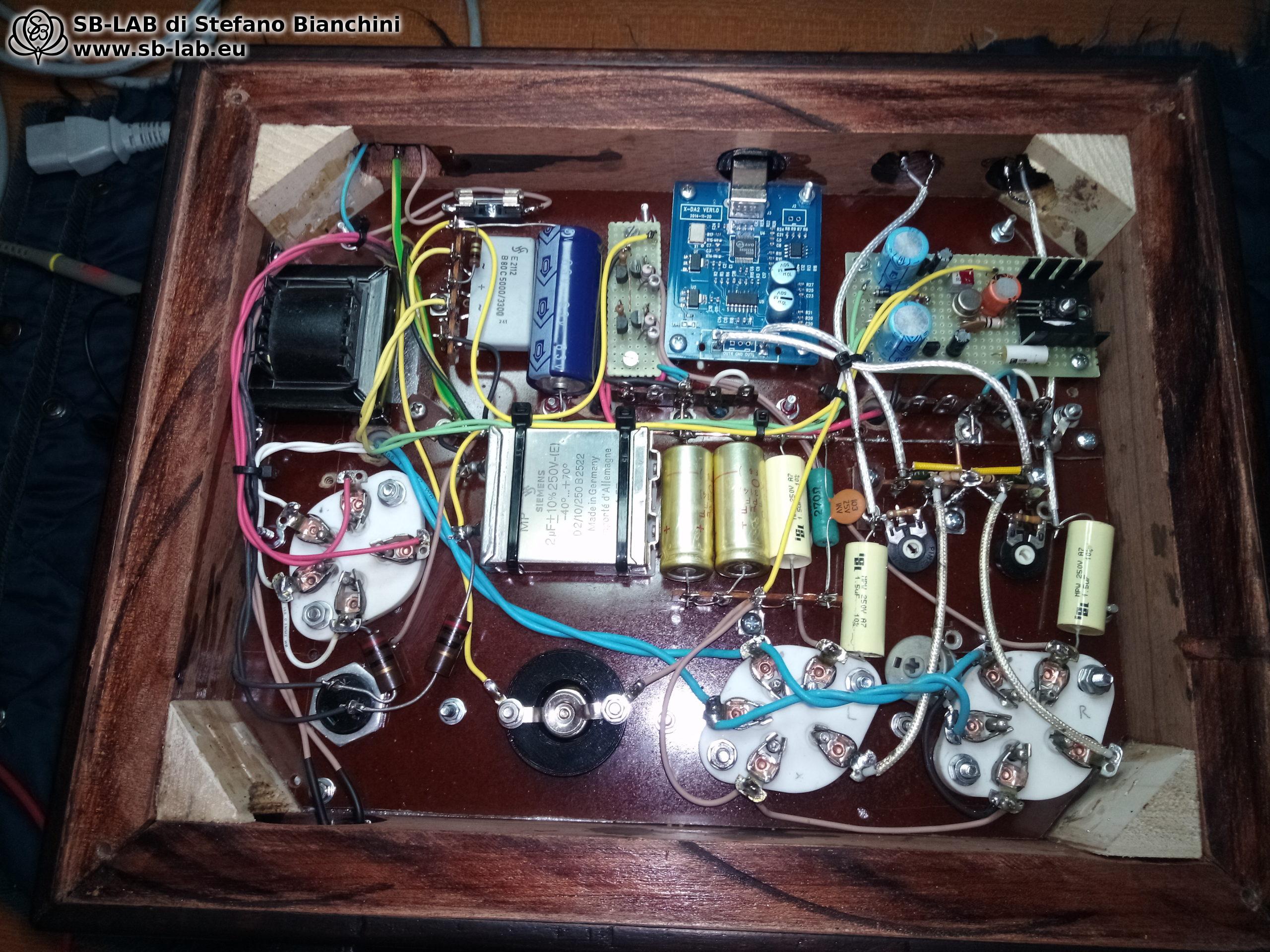
Unlike a pure resistor load, a CCS does not lose all the benefits you get from an inductive load and probably preserves more detail. I added two small trimmers to balance the channels because the feedback is obviously minimal (as explained in the Nibiru project) and can’t perfectly equalize channel levels. The UY227s are nearly a century old, and expecting a perfect match is, frankly, wishful thinking — solvable only by spending a lot (with no guarantee the match will hold). But I had these two at home; the channel difference was only about 0.2 dB, so adding that 2.2 M? trimmer for a micro-adjustment is nothing that would compromise sound quality. In the end, this “centenarian” DAC has a truly airy, very clean, and brilliant sound. Compared with other builds of mine, the treble is smoother — perhaps thanks to the ICEL coupling caps or the paper-in-oil in the PSU. I want to try paper-in-oil on the signal path too — I have them — but in due time (I also have to work 🙄 ). So even if it remains a box with 6 kilos of disconnected line transformers inside serving only as decoration, I’m still satisfied with the result. I won’t fail to try other approaches in the future — probably a parafeed in pure Nibiru style using my 18S100, or rebuilding the same project with better transformer spacing (since the 26 prototype didn’t have this issue).

Here is the premium schematic for those who want to build my circuit. The kit to build this DAC consists of a power transformer and a choke; the two SB-LAB line transformers are also available, but you must install them at least 15 cm away from the power transformer. You can also use other DACs or add RCA inputs to connect an external source. The circuit gain is 15 dB when configured with the CCS or a choke load.

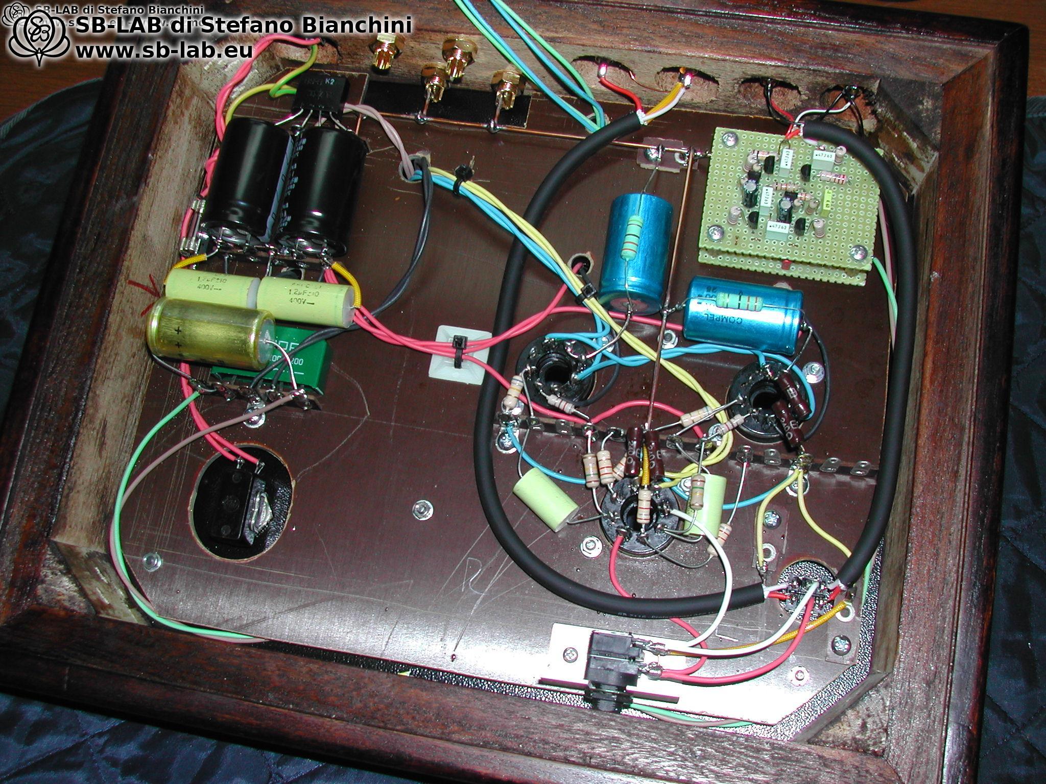
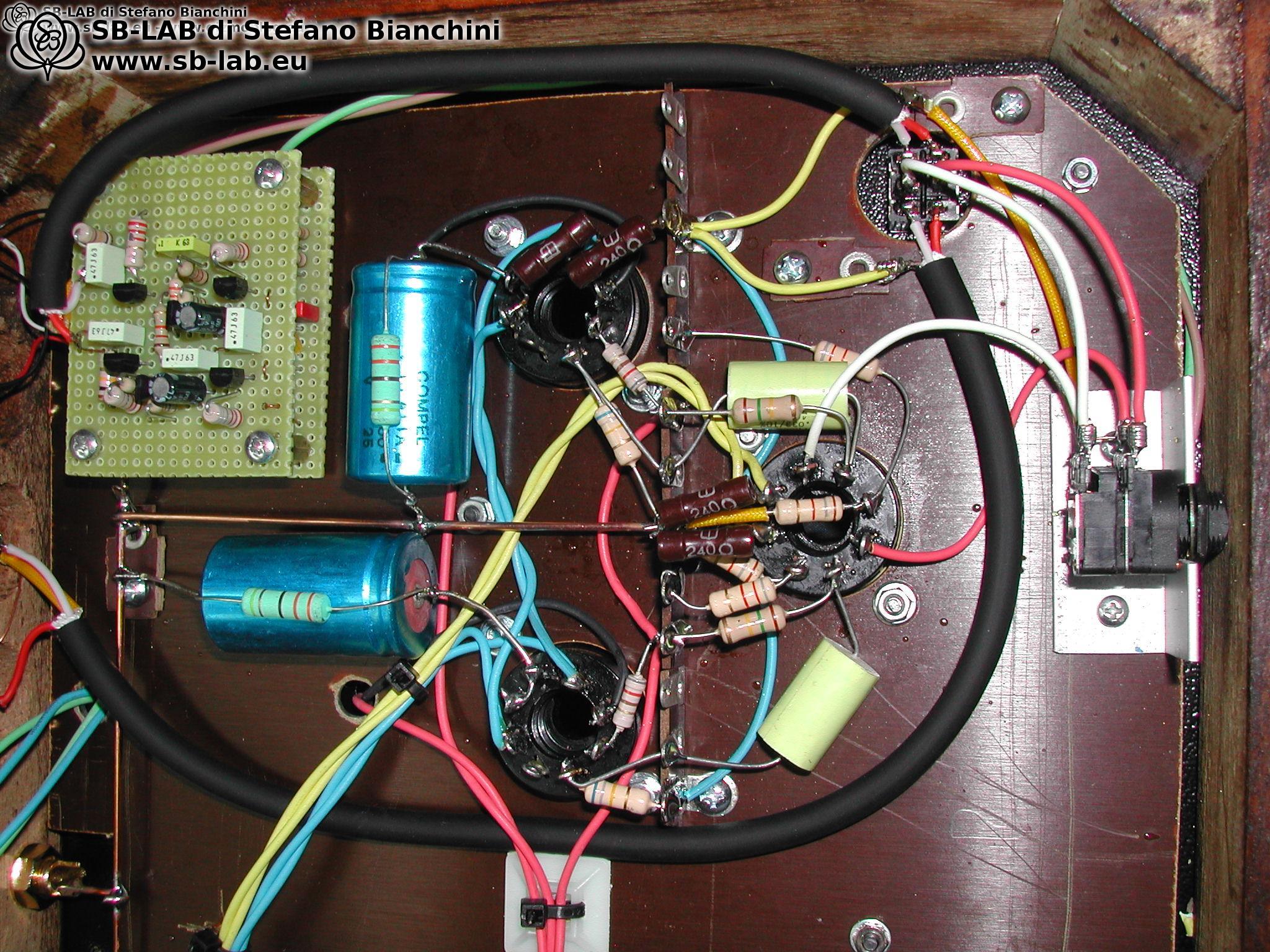
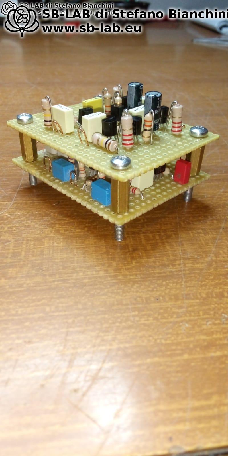
More photos of my build
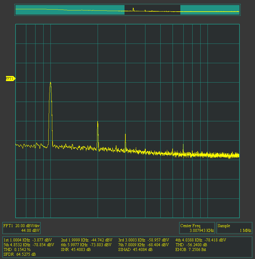
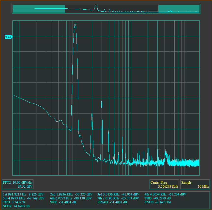
Some measurements… Below is the spectrum analysis of the Sabre 9023P DAC alone, showing virtually zero distortion:
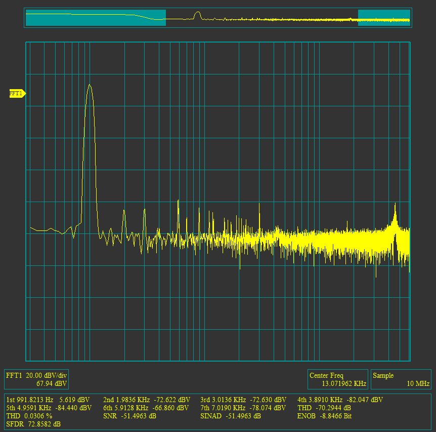
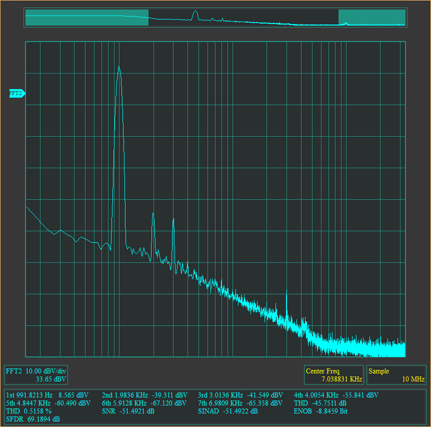
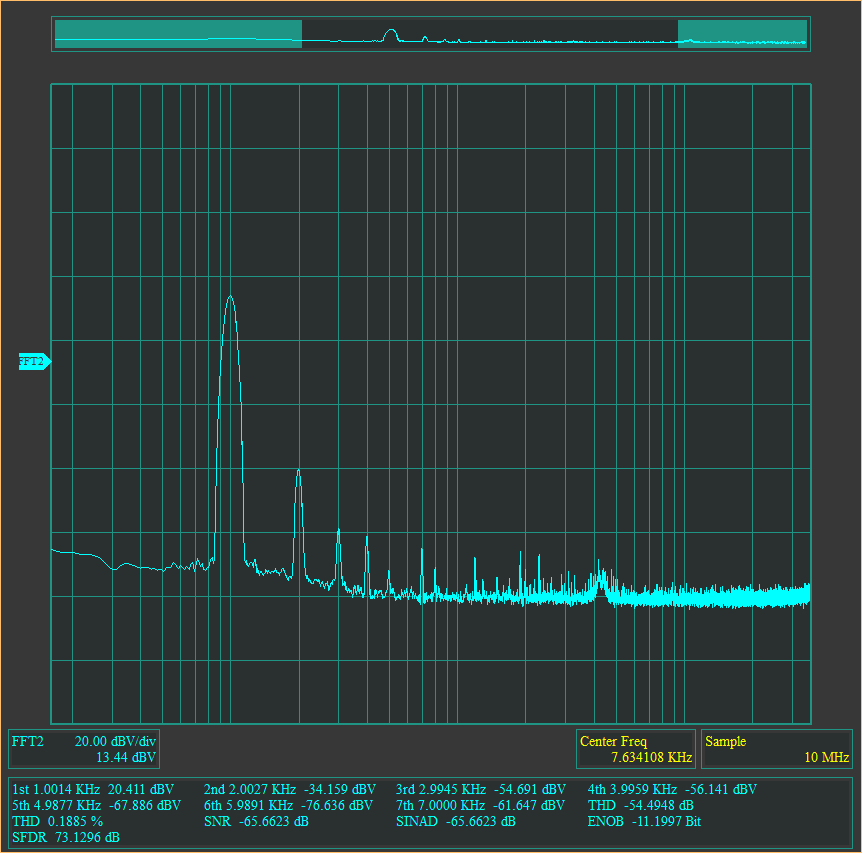
This, instead, is the spectrum of the circuit with the UY227 at 30 Vpp output amplitude, showing 0.18% distortion…
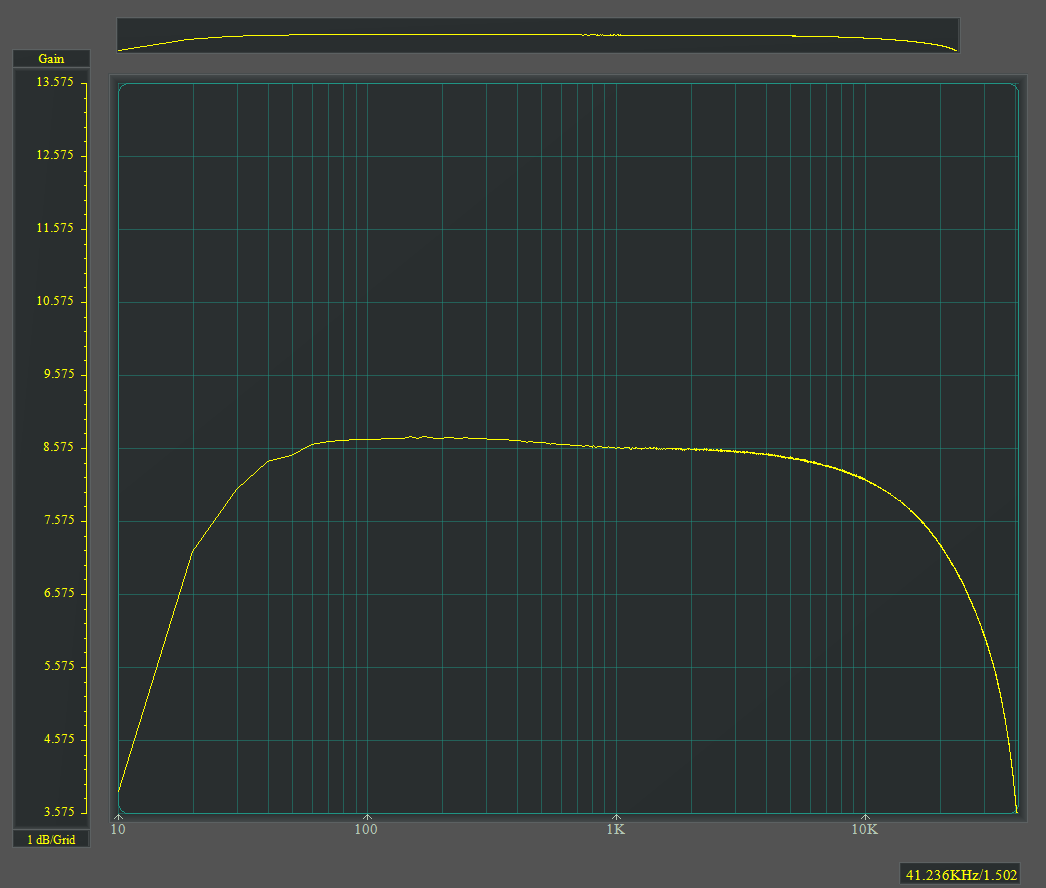
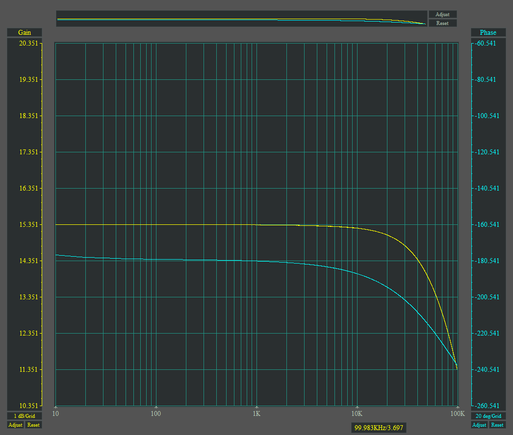
The bandwidth of the circuit with the UY227 loaded by the CCS is 10 Hz 0 dB – 40 kHz –1 dB…
Continue reading...

Leave a Reply

This site uses Akismet to reduce spam. Learn how your comment data is processed.

SB Varuna “Phono” – Single-Ended 6V6GT

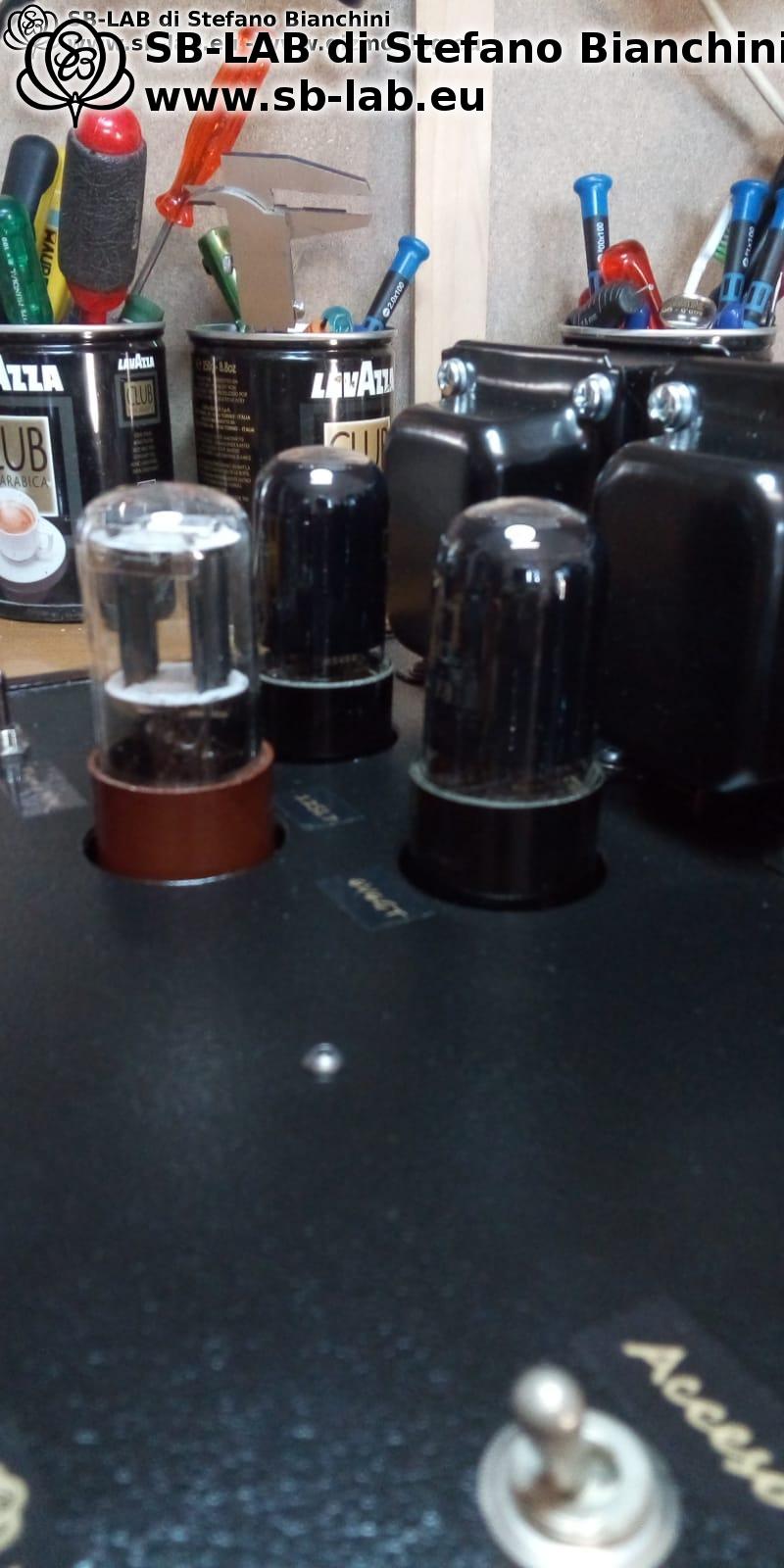
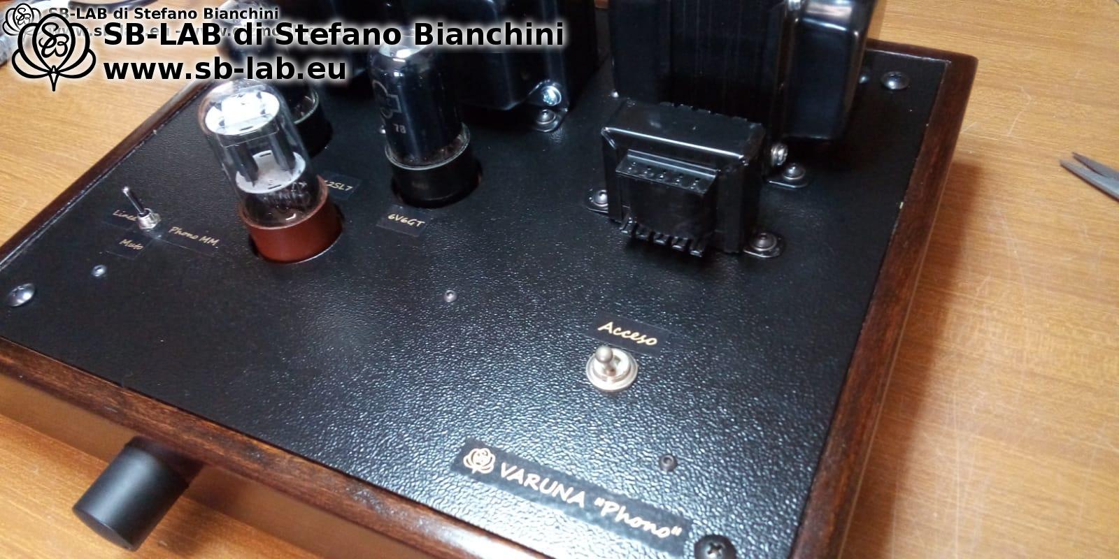
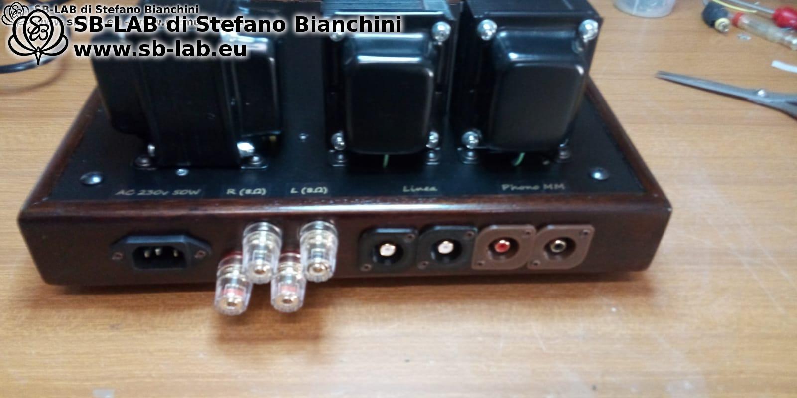
For some time I wanted to build something using 6V6 tubes, so when I found a nice pair of NOS 6V6s at a flea market, I took the opportunity. I also wanted it to include a phono input for an MM turntable but remain simple to build. I therefore decided on a very straightforward single-ended design using a 12SL7 at the input (one triode per channel) and 6V6GT tubes strictly connected as pentodes in the output stage. The output transformer is the well-proven SE5K6-UNI. For the phono section, I built a small discrete solid-state preamplifier specifically for this project.

Let’s start with the phono module, designed exclusively for MM cartridges:

Here is the spectrum analysis of the standalone RIAA module:

The amplifier was assembled on a wooden frame — below you can see the build process:

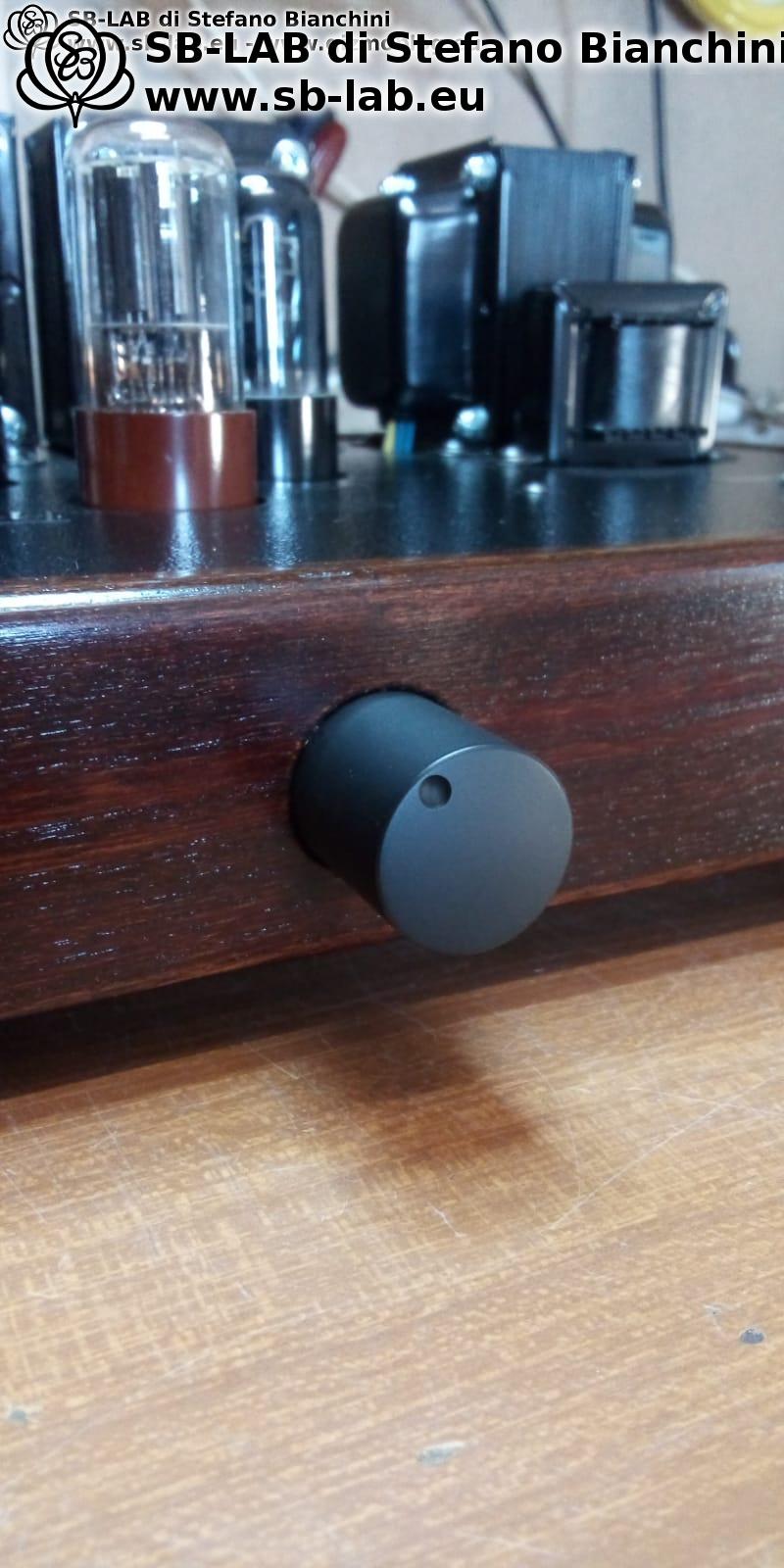
And here’s how it looks from the outside:

The tonal character of this amplifier was intentionally made (by circuit design) less bright and rounder in the high range, as I wanted to use it with high-efficiency speakers (Klipschorn Heresy) with horn tweeters. The feedback ratio is minimal, since these speakers are known to be somewhat lacking in the low range.

Measurements
Power: 2.85 W RMS per channel @ 3 Vpp input
Damping factor (DF): 4.0
THD @ 1 W: 0.5%

Frequency response @ 1 W (line input)

Frequency response through the phono preamp (reverse RIAA applied, phase omitted as it is inverting)

Square wave @ 1 kHz and 10 kHz

Spectrum analysis @ 1 W (line input)

Spectrum analysis @ 1 W (phono input)

How does it sound? The bass is definitely there, and the volume is impressive — with just 3 watts, the room fills with powerful, pleasant music. Highs and lows are both well defined, voices are warm and present, and you start wondering why anyone needs more powerful amplifiers. I paired it with the USB Mini DAC and started with Beethoven’s Ninth Symphony — which honestly sounded awful (probably a poor CD), but then I tried Vivaldi’s Four Seasons and, together with my friends — including a professional orchestra musician — we all fell silent, amazed by the beauty of the sound. Then I played Pink Floyd and other bands, as well as modern singers — everything sounded rich and enjoyable. I brought the amp to some friends’ houses and tested it with various speakers, including JBL LX66, and it always sounded delightful — with the floors vibrating from the bass. In short, a project I’m truly proud of.

Continue reading...

Leave a Reply

This site uses Akismet to reduce spam. Learn how your comment data is processed.

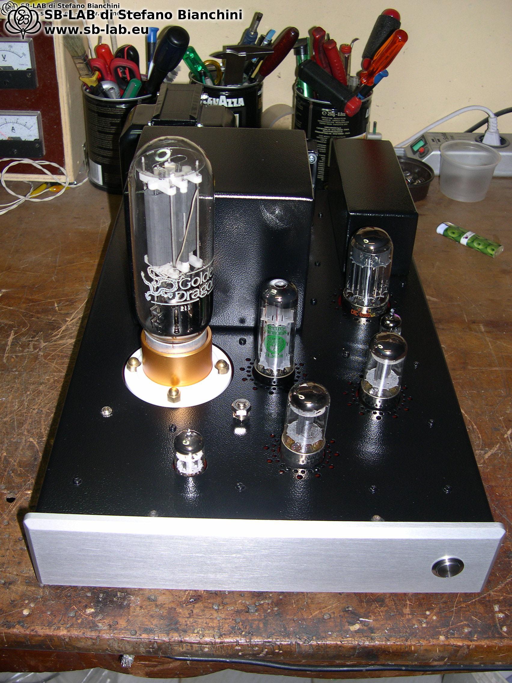
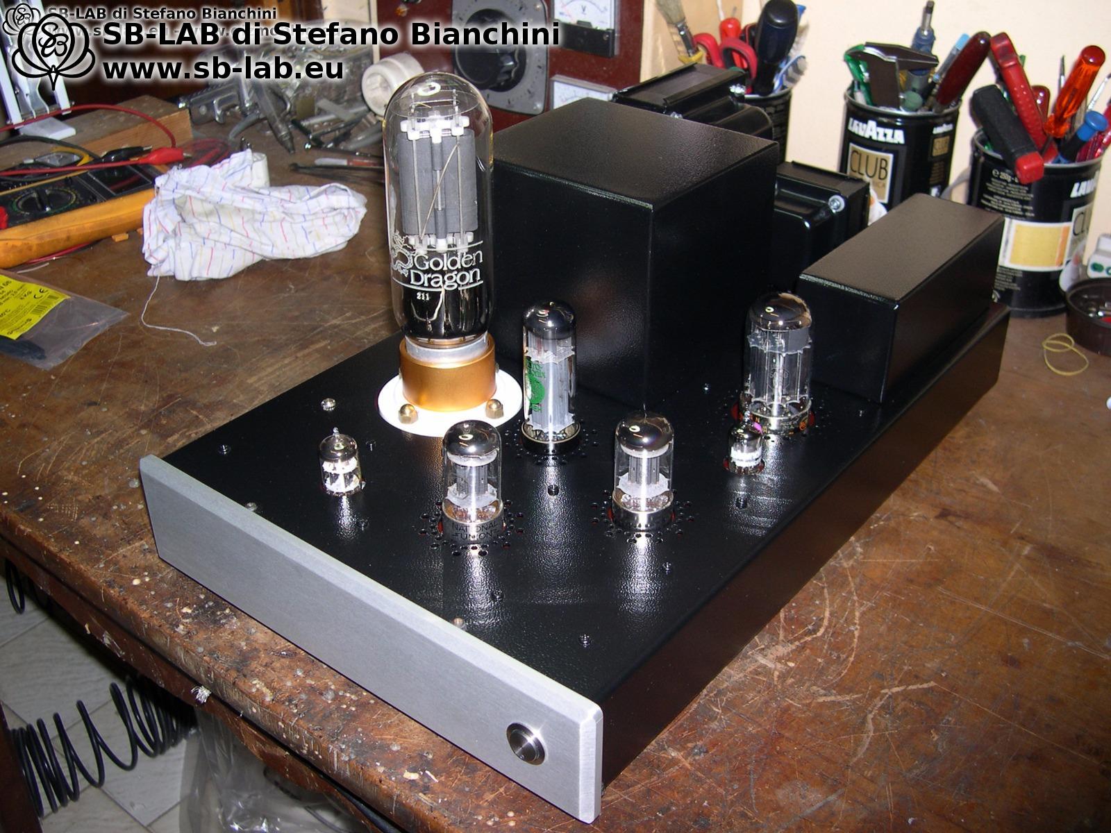
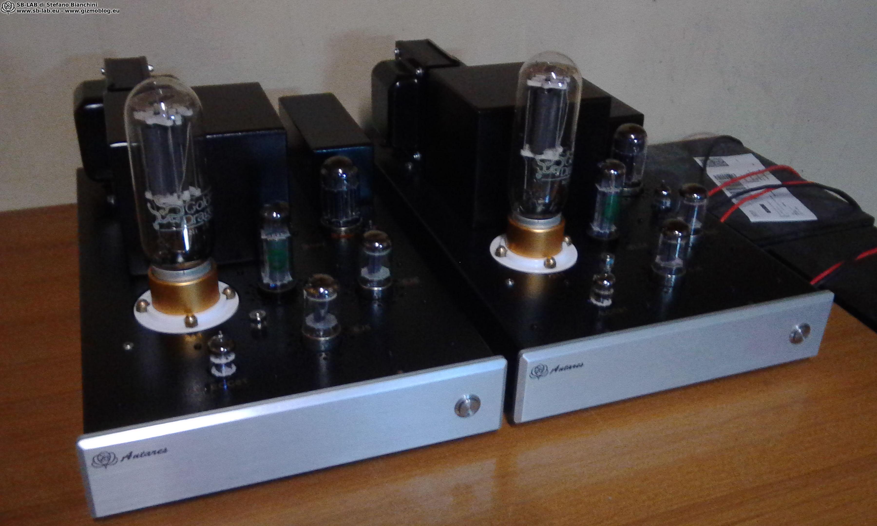
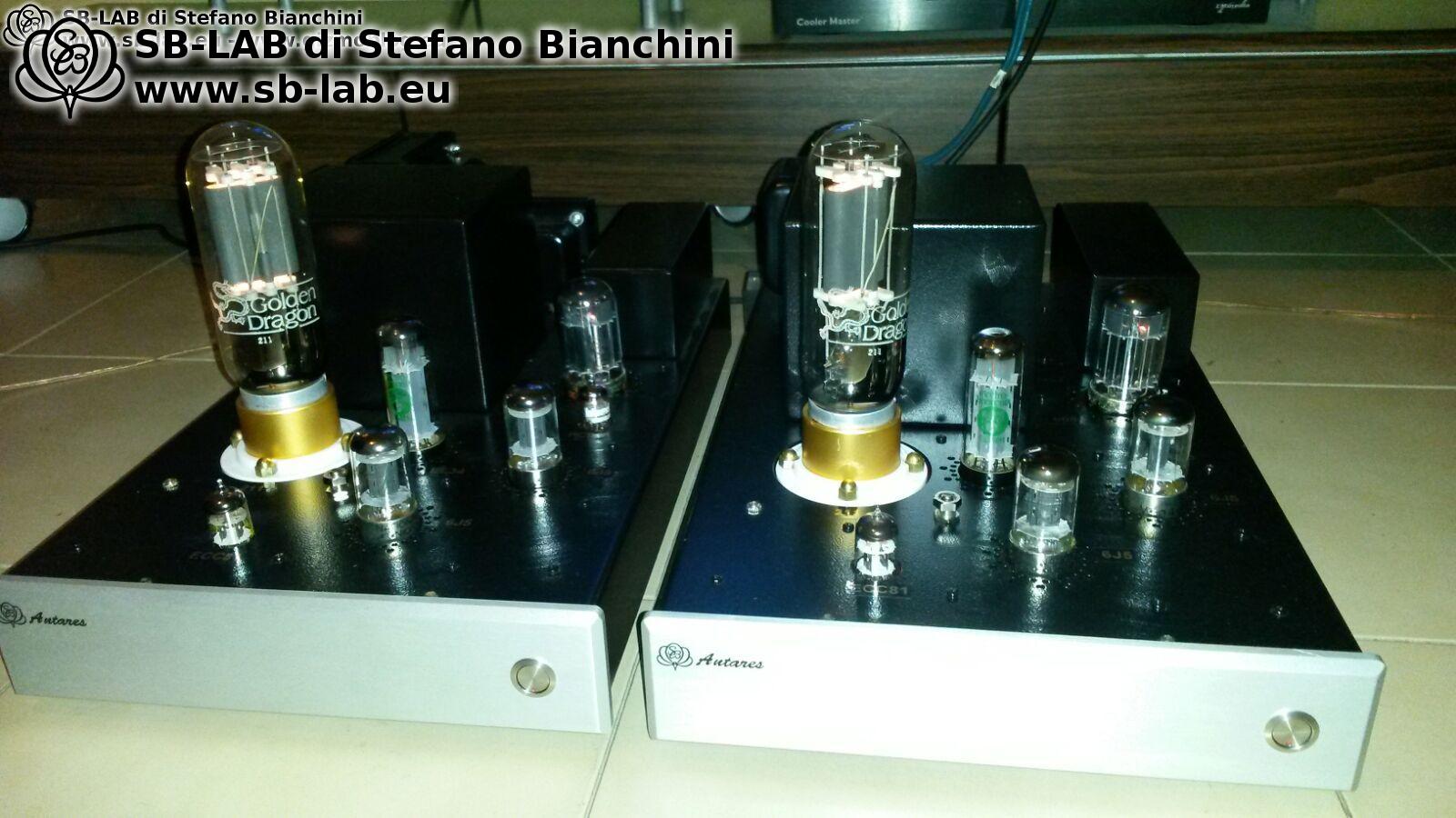
SB Antares, single ended 211 VT-4C monoblock amplifiers in class A2

Building a single ended amplifier using the 211 tube is not, for me, just a “more powerful variant” of the usual triode projects. It is a different path altogether, with precise rules, real compromises, and very high stakes. The 211 (VT-4C) is a historic tube, fascinating and demanding, capable of enormous sonic scale and dynamics that, if handled correctly, can challenge many more modern solutions. But precisely because it is a “large” tube, it demands to be treated with respect: high voltages, proper insulation and safety margins, serious drive capability, transformers up to the task, and a power supply that does not collapse when things get difficult.

This article documents an old SB-LAB project dating back to 2017, completed after a long gestation period of almost ten months, including calculations, prototyping, transformer design, and mechanical construction. The photos you see therefore belong to that specific period and to that exact version. If I were to rebuild these monoblocks today, I would not make them identical. The core concept would remain the same, but several details would be revised and improved to reflect everything I have learned over the years, both electrically and mechanically, including internal layout and optimization of grounding paths and wiring. This is exactly the beauty of “important” projects: they are never truly finished, they are milestones that teach you something, and over time they show you what you would do better today.

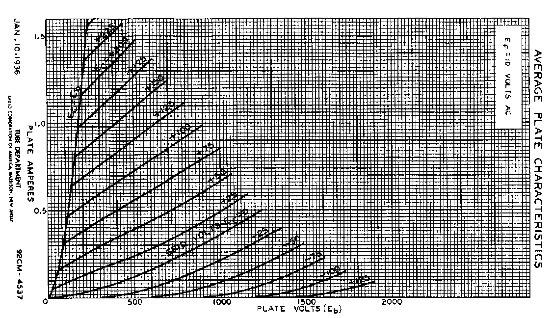
After almost ten months of development, I finally brought these two single ended monoblocks with 211 tubes to life. The project was anything but simple. I wanted to use the 211 properly, and by “properly” I mean that a tube of this size cannot be reduced to delivering 10 watts, as many do simply because they are unable to design a proper driver stage. According to the datasheet, the 211 requires and expects mixed A1+A2 operation, with both negative and positive grid operation. If you disagree with this, my suggestion is to use an 845 instead. For this reason, weak driver stages and interstage transformer coupling were ruled out from the start, as they tend to smear the sound, limit bandwidth, and prevent proper control when the grid swings positive.

When discussing the 211, many people focus immediately on anode voltage and output power, but the truly critical point, the one that separates a “clever” design from a well executed one, is the driver stage. The reason is simple: the 211 is not a tube that is satisfied with a modest voltage swing. If you want it to operate in its natural territory, you must provide wide excursions and, above all, maintain linearity when the load becomes brutal, that is when the grid starts drawing current. That is where many circuits collapse, compress, distort, or become unstable. The goal of this project was very clear: to control the 211 even when it enters A2 operation, without losing grip, without smearing the upper range, and without letting the low end fall apart when current demand becomes real.

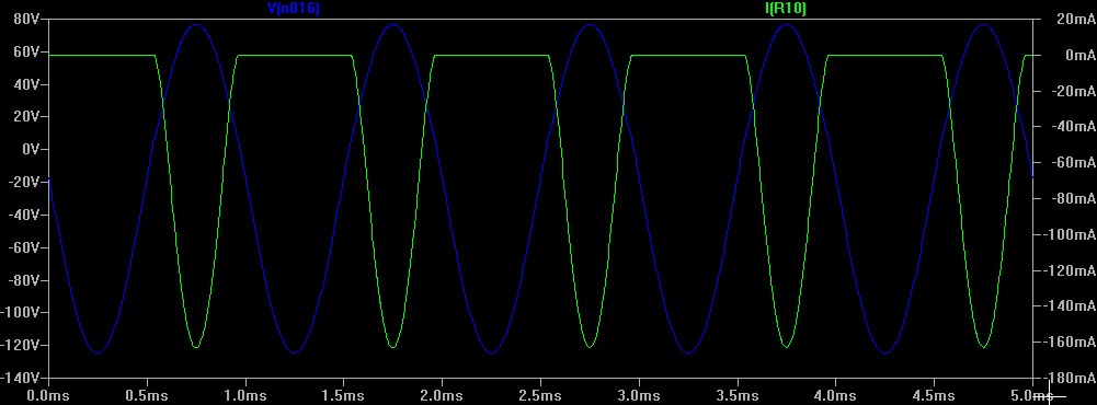
The project started on paper, and I had to think carefully about the schematic because a very large voltage swing was required, one that remained linear into a strongly non linear load represented by the G1 grid of the 211. This grid draws virtually 0 mA over the entire negative swing, then increases up to a maximum of 160 mA during positive swing. The behavior of my circuit is shown in the graph below, where the signal waveform is shown in blue and remains linear, while the grid current of the 211 is shown in green and is clearly non linear. This circuit delivers 25 watts RMS with 850 volts of anode voltage into a 9k load. It would be possible to increase output power to about 35 watts RMS by raising the supply to 1000 or 1200 volts, but I chose not to, because this would have required series connected capacitors in the power supply, which in my opinion could have compromised sound quality. The current supply uses a voltage doubler followed by an LC filter with a 200 uF, 1000 volt polypropylene capacitor.

Here lies one of the key points. As long as the grid of the 211 remains negative, it is almost “invisible” to the driver stage, and many amplifiers deliberately stop there to avoid complications. But if you truly want to use the 211 with authority, you must accept that in A2 operation the grid becomes a current drawing load, and a highly non linear one. This means the driver must not only supply voltage, but also current, and it must do so without being pulled out of linear operation. In other words, it is not enough to simply reach the required voltage, it must reach it properly, with margin and control, and without letting distortion run away.

I chose 850 volts and a 9k load because this represented a well reasoned balance between power, electrical stress, insulation, long term reliability, and power supply quality. Yes, increasing the anode voltage to 1000 or 1200 volts would increase power, but at that point many things change: clearances, component availability, transient management, and above all you enter a territory where the power supply must be even more monolithic to avoid betraying the design. At that stage, I preferred to stop where I could guarantee a truly solid, high quality supply, without compromises such as series electrolytics which, although manageable, were not what I wanted in a project of this kind.

The graph visually summarizes the goal: keeping the signal waveform clean even while grid current becomes a dominant factor. In listening terms, this translates into the absence of compression on peaks, better control of dynamic swings, and that sense of authority which, in well designed single ended amplifiers, does not depend on nominal power but on how the circuit behaves when the music becomes demanding.

After finalizing the circuit from a theoretical standpoint, I built the transformers and moved on to the CAD design of the amplifiers.

In a project like this, the magnetic components are not an “accessory”, they are an integral part of the result. Output transformer, filter chokes, power transformer, and the management of parasitic capacitances and leakage all determine bandwidth, stability, noise floor, and transient behavior. CAD design in this context is not just about fitting everything inside a chassis. It is about deciding signal paths, distances, shielding, core orientation, and management of stray fields. These are all aspects that, if underestimated, will come back to haunt you later, when you are already at the end of the project and chasing hum or unwanted coupling.

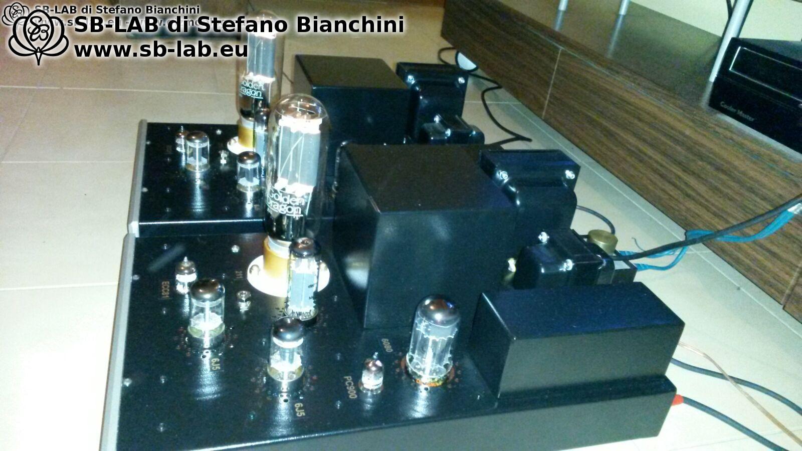
And then came the physical construction. Mechanical execution, especially with such high voltages, is a chapter of its own. This is not only about aesthetics. Wiring, insulation, choice of grommets, distances between points at different potentials, mounting methods, ventilation, and accessibility for maintenance are all critical. A 211 amplifier must not only look good and sound good, it must also be built in a way that avoids unpleasant surprises over time, especially considering the energy involved and the transients during power up and power down.

The following images, as mentioned earlier, belong to the original project. They document a real journey, with the solutions of that specific moment in time. If I were to revisit this design today, some choices would certainly be refined, not because they were “wrong”, but because accumulated experience inevitably leads you to optimize details that may not have been priorities back then. This applies to internal layout, certain grounding paths, management of parasitic capacitances, serviceability, and also conservative choices in components and wiring, in order to make the project even more robust without altering its core character.

Instrumental Measurements
Power 25 watts RMS
Bandwidth at 1 watt: 15 Hz – 50 kHz -3 dB
Bandwidth at 25 watts: 30 Hz – 22 kHz -3 dB
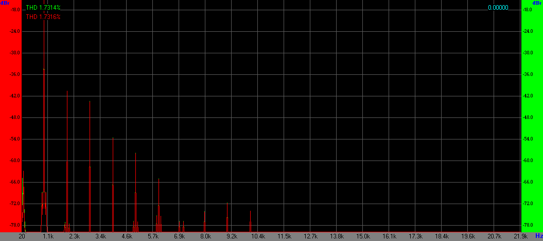
THD at 1 watt: 0.3%
THD at 6 watts: 1.7%
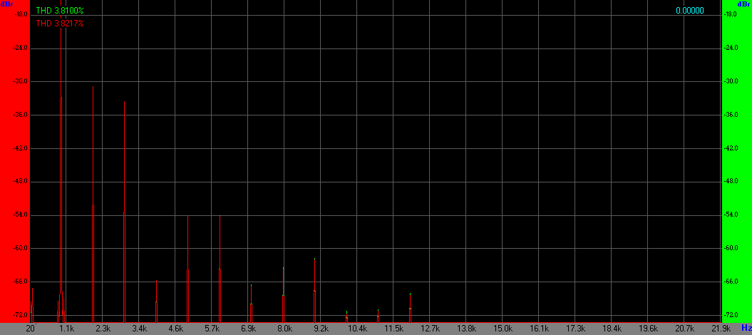
THD at 15 watts: 3.8%
Damping factor: 5
Rout: 1.6 ohm

Instrumental measurements must be interpreted in the proper context. In a single ended triode amplifier of this type, nominal power does not tell the whole story. What matters is how distortion rises with power, how bandwidth behaves near the limits, and above all stability and transient response. The damping factor here is not particularly high, and it does not have to be, but it is sufficient to provide credible control with many loudspeakers.

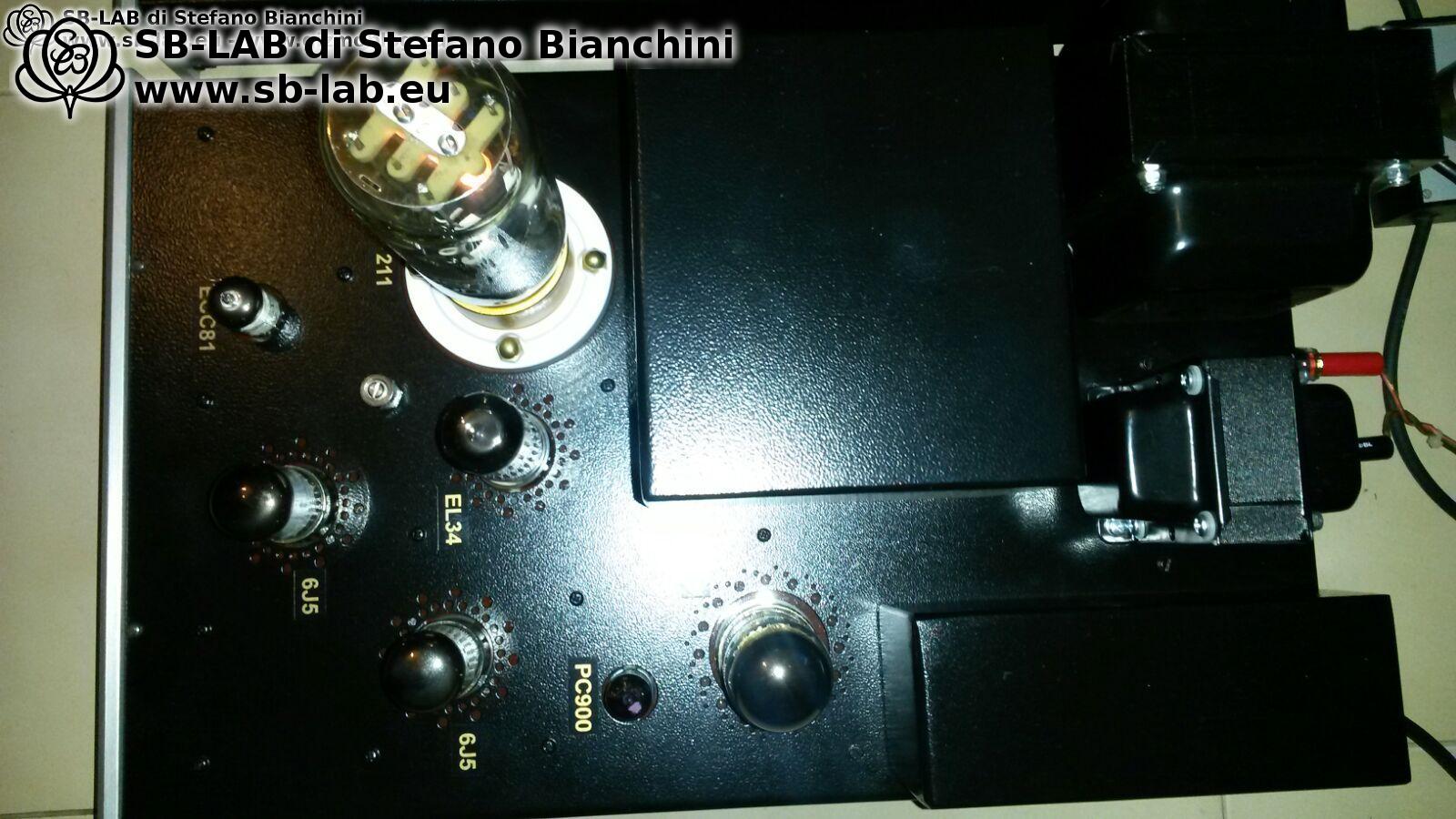
Tubes used 7
1x 12AT7 / ECC81: input stage, excluded from the global NFB loop
2x 6J5: voltage gain
1x EL34 triode connected: follower, driver, bias control, DC coupled to the output tube
1x 6080: voltage regulator for the EL34 anode supply
1x PC900: error amplifier driving the 6080
1x 211 / VT-4C: output tube

The tube chain was chosen with a very specific goal: to reach the 211 with a driver stage capable of wide voltage swing and current delivery, while maintaining a controllable and stable structure. Excluding the input stage from the global feedback loop helps preserve its behavior and sonic character, preventing feedback from indiscriminately affecting everything. The pair of 6J5 tubes provides voltage gain in a clean and predictable way, while the triode connected EL34 does the heavy lifting: following, driving, and managing bias via DC coupling to the output tube. In a design that must enter A2 operation, this is not a minor detail. Coupling and operating point stability must remain solid even when the 211 grid starts drawing significant current.

The stabilization section using the 6080 and PC900 was designed to keep the driver supply consistent, because driver linearity and stability also depend on how much its high voltage moves with load variations. In practice, it is not enough to design a good driver, you must also prevent the power supply from turning it into something else when you turn up the volume.

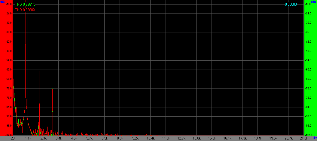
Spectrum at 1 watt

Spectrum at 6 watts

Spectrum at 15 watts

At high power levels the spectrum shows how well the system remains under control near saturation and how credibly A2 operation is handled. This is where the value of a serious driver becomes clear. When the circuit is designed for this region, there is no sudden change in character, no nervous compression, and the music retains a natural quality that is often missing in designs that avoid A2 out of fear of complexity.

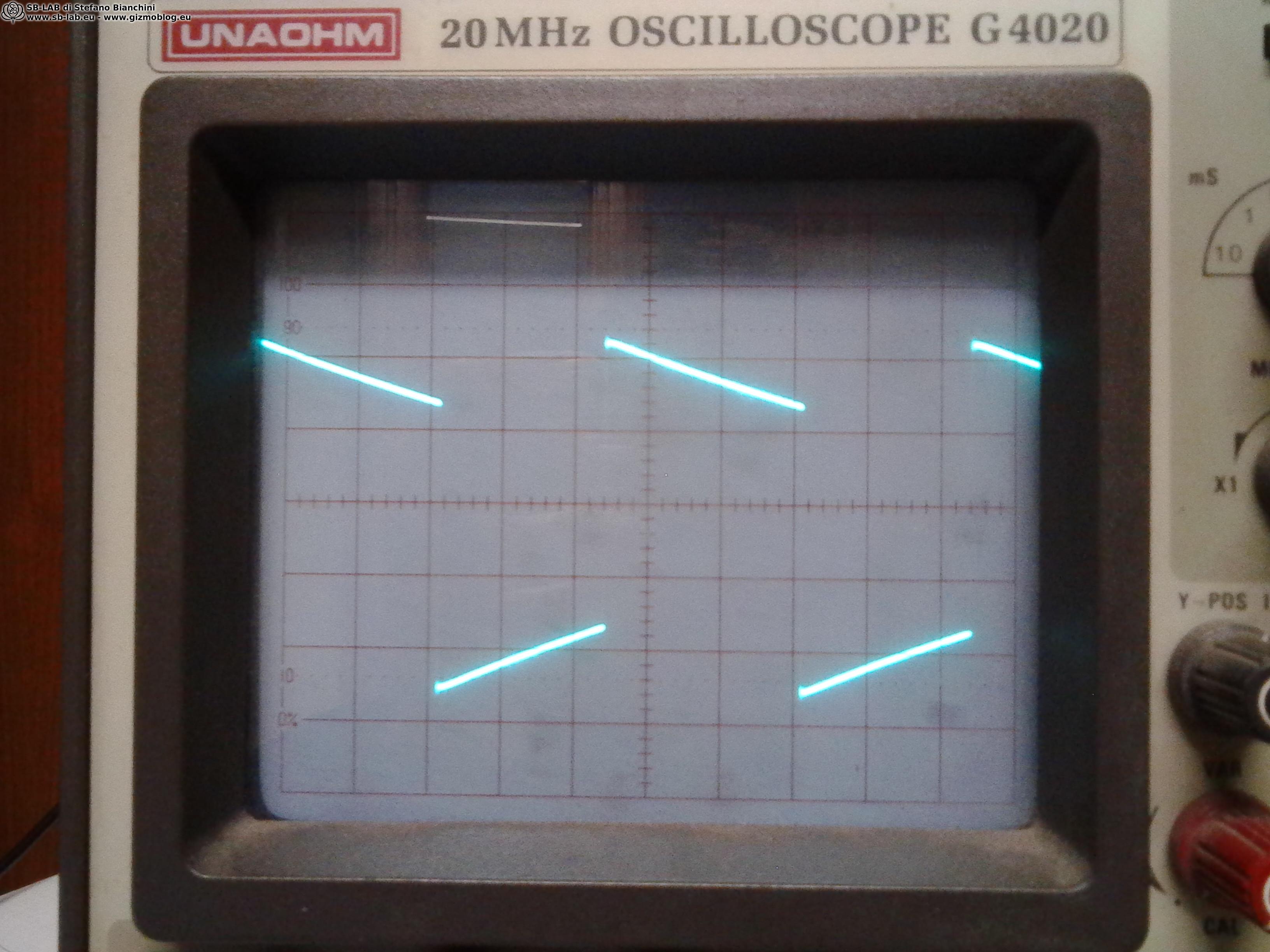
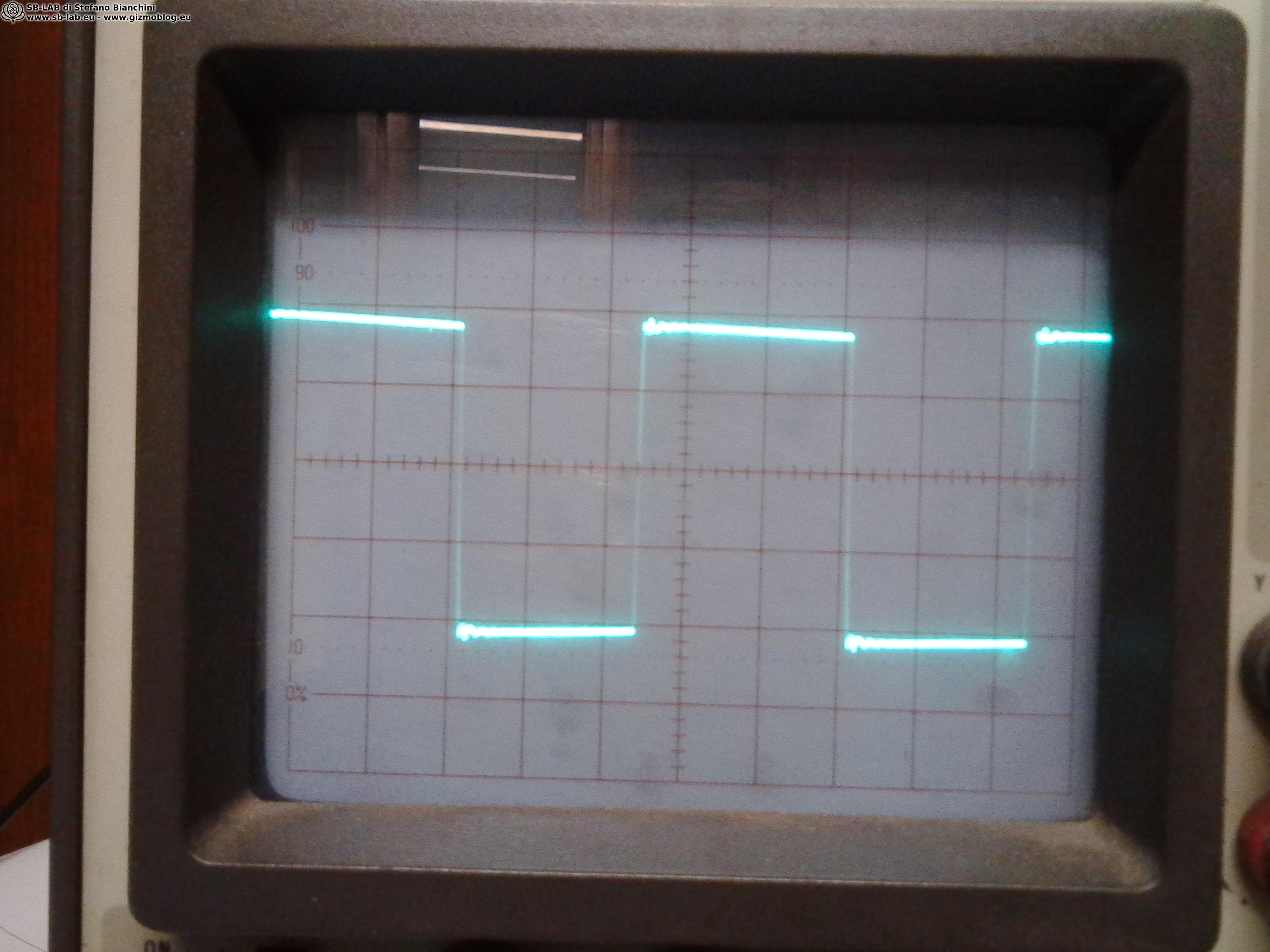
Square wave at 100 Hz

Square wave at 1 kHz

Square wave at 10 kHz

At 10 kHz the square wave is a severe test, because it highlights real bandwidth limits, parasitic capacitances, leakage, and compensation. A clean result here is not just nice to look at. It is often correlated with more believable harmonic decay, sharper transients, and a clearer soundstage, without resorting to an over analytical sound that later leads to listening fatigue.

How does it sound. The first impression was that these were truly big amplifiers, and after long term listening they absolutely are. In my controlled environment, after many tests and recordings, I can only say they are even better than they initially appeared. They deliver an imposing yet always refined mid and high range, and a bass that is solid and statuesque. They are melodic and rich in detail, and with certain recordings you can hear the pianist breathe, the guitarist resting their hands on the instrument. I have no doubt placing them among the best amplifiers I have ever had the chance to build and listen to. It is hard to explain, but when you encounter amplifications like this, you realize that everything you once thought was immense was, in reality, only big. The effort required for such a demanding build was absolutely worth it.

With hindsight, I would add one important observation. The sonic character of a 211 single ended amplifier is not just about power and presence. It is about authority, continuity, and naturalness when the music moves from pianissimo to fortissimo without changing character. With these monoblocks, the sensation is one of reserve, not so much in watts, but in control. The mid high range is wide and luminous, yet never sharp, and when the recording is good, a microdynamic quality emerges that lets you perceive gestures, breaths, nuances, and space in a very physical way. The bass, when the loudspeaker allows it, is not only extended, it is firm, articulated, and readable. This kind of solidity does not come from emphasis or excess, but from a circuit that does not lose its grip when the demands become serious.

If I were to revisit this design today, I would work even more on certain construction and optimization details, because that is where the real progress is made. But one thing would not change: the core idea of treating the 211 with the respect it deserves, with a driver worthy of A2 operation, transformers designed for this mission, and a power supply that is not an accessory, but an integral part of the sound.

Continue reading...

Leave a Reply

This site uses Akismet to reduce spam. Learn how your comment data is processed.