The bandwidth of an amplifier represents the range of frequencies that the device can reproduce while maintaining a given attenuation tolerance. In HiFi, a useful response is normally considered to be at least from 20 Hz to 20 kHz, but this figure alone says very little unless the measurement conditions are also stated: attenuation, power, applied load and signal level.
Many people believe that it is enough for an output transformer to reach 20 kHz to be free from problems. This is wrong reasoning. An audio transformer does not only introduce attenuation: it also introduces phase shifts, losses, resonances and distortion that can begin well before the declared bandwidth limit. For this reason, a good output transformer must have a wider bandwidth than the audible range alone, not because it is necessary to reproduce ultrasonic frequencies, but because this allows the audible part of the signal to remain cleaner and more correct.
Web Myths
Every now and then you read that an overly wide bandwidth would even be a defect. Put this way, it is nonsense. It can make sense to intentionally limit the bandwidth in the circuit, for example to avoid instability, RF interference or unnecessary stress on tweeters, but it makes no sense to want an output transformer that is already limited by itself. The transformer must be as transparent as possible in its working range; any limitations must be decided by the designer in the circuit, not endured because the component is poor.
To support this concept, I will use the example of a Tamura transformer, one of the most important names in the audio transformer field. So we are not talking about forum chatter, but about real, expensive products that are recognized worldwide.
Click to enlarge
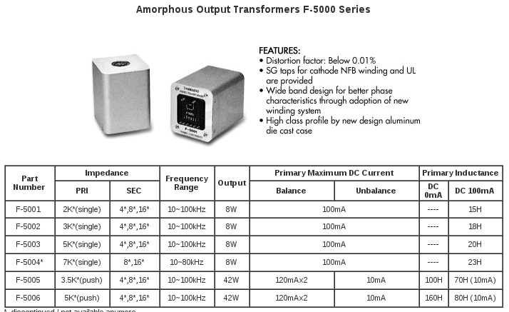
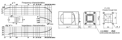
The transformers in this family are sold at significant prices. From the table, you can see that some models have a very extended response, specified up to 100 kHz with limited attenuation. This shows one simple thing: the best manufacturers do not look for transformers that stop just above 20 kHz. They look for transformers that work well far beyond that, precisely to keep the audible range correct.
The problem is that many people get their information from forums, where correct information and legends are constantly mixed together. You can read claims such as: the primary and secondary must be interleaved 20 or 30 times, at least 100 Henry of primary inductance are needed, the transformers of the two channels must have identical inductances otherwise they will sound completely different, and so on.
Reality is less fanciful and much more practical. An output transformer must be evaluated by looking at its real response, attenuation, phase, square wave behavior, the load it was designed for and the measurement conditions. A declared bandwidth without stating the attenuation means nothing. Writing “20 Hz – 20 kHz” without saying whether it is at -1 dB, -3 dB, -6 dB, at what power and on what load, is incomplete data.
Personally, I always try to declare the measurement conditions clearly. Not because the number alone makes the sound, but because without serious numbers you remain in the field of impressions, marketing and clichés.
I am pleased to share my experience in building audio transformers. As a passionate craftsman, I have devoted a great deal of effort to perfecting the design and construction of these crucial components. Over time, I have managed to achieve results that, in some cases, can compete with transformers made by renowned brands such as Tamura.
I do not intend to belittle historic brands such as Tamura, Tango, Hashimoto or other serious manufacturers. On the contrary, they are important references. What I am saying is that, with work, testing and real measurements, even a small workshop can achieve high-level results. Slogans are not needed: what is needed are transformers that, once put on the test bench, prove what they promise.
A Little Clarity About Interleaving
An important aspect in the design of an audio transformer is sectioning, meaning the interleaving of several primary and secondary sections. This technique is used to improve coupling between the windings, reduce leakage inductance and improve high-frequency transmission.
As often happens, however, the rule “the more, the better” does not apply. Too much interleaving can become counterproductive. As the number of sections increases, the coupled surface between the windings also increases, and therefore parasitic capacitances increase. These capacitances worsen high-frequency behavior and can cause resonances, attenuation and instability.
The correct number of sections depends on the transformer: transformation ratio, primary impedance, number of turns, power, type of core and valve used. It makes no sense to decide in advance that a good transformer must have 10, 20 or 30 sections. You have to measure and find the right balance.
If a first prototype shows a very wide bandwidth but coupling that can be improved, it may make sense to increase the sectioning. If, on the other hand, the transformer is already limited at the top end, increasing the sections even further will make the problem worse. In that case, the parasitic capacitances must be reduced or the construction layout must be revised.
In general, a single-ended transformer can work very well with about 5 or 6 sections. A push-pull transformer may require something more, for example 10 or 12 sections. This is not a universal law, but it is a realistic order of magnitude. Huge numbers, flaunted as proof of quality, are often just marketing.
I would like to share with you the construction diagram of a Conrad Johnson MV50 amplifier. However, to protect my work and avoid making sensitive details such as the number of turns and wire sections accessible, I have censored that information. I spent an entire day making this diagram, obtained by unwinding a damaged transformer. I do not disclose the diagrams of my transformers, but this example serves to make the concept clear. This is the transformer of a commercial Conrad Johnson MV50 amplifier, appreciated by many, yet built with a number of sections that is anything but exaggerated.
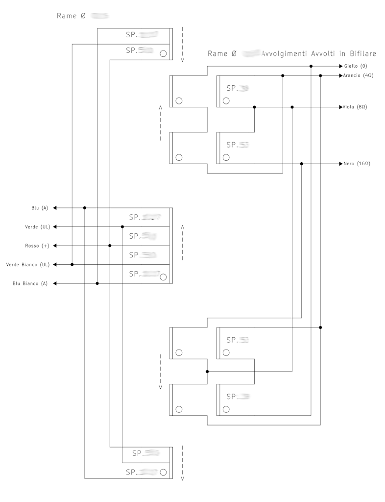
When I hear talk of transformers with 30 or 35 sections, I have to laugh. I am not saying that they are physically impossible to make, but then you have to see how they really behave. A transformer does not become good because it has many layers or many sections: it becomes good if it measures well, works well with the intended valve and does not introduce defects into the signal.
A Little Clarity About Primary Inductance
The primary inductance of an output transformer must be suited to the valve, the primary impedance, the power and the minimum frequency you want to reproduce. It is not a number to be chosen at will.
If a transformer designed for a certain valve can correctly reproduce 10 Hz with 20 Henry of primary inductance, there is no point in insisting on 80 or 100 Henry. Unnecessarily increasing the number of turns brings disadvantages: higher copper resistance, higher parasitic capacitances, worsening of the high-frequency response and a greater risk of core-related problems.
The correct value also depends on the internal resistance of the valve. A triode such as the 2A3, with low internal resistance, requires a lower primary inductance than a valve with much higher internal resistance. This is why it makes no sense to copy a value seen on a forum and expect it to be valid for any transformer.
The 100 Henry Primary Inductance and the Myth Born from Simulations
Many people ask me why, in my price lists, I declare the bandwidth of transformers but not always the primary inductance. The reason is simple: that number, read on its own, is often misunderstood. In particular, some simulation software such as Spice and LTspice have unintentionally helped create the myth that enormous inductances are always needed.
LTspice is excellent software, which I also use, but it must be understood. Properly simulating an audio output transformer does not mean simply drawing two coupled inductors. A real transformer has resistances, leakage inductances, parasitic capacitances between turns, between windings, toward the core, magnetic losses, non-linear core behavior and much more.
In my tests, I have tried several times to enter values measured on real transformers into LTspice: inductance, DC resistance, losses, parasitic capacitances and other parameters. However, the result never matched the real behavior of the transformer on the test bench perfectly. In simulation, it often seemed that the primary inductance was insufficient, while in the real circuit the transformer worked correctly.
So, to make a quick simulation of a valve amplifier, you often end up using very high values, for example 100 Henry, not because the real transformer must necessarily have that value, but because the simplified model requires a convenient approximation so as not to distort the rest of the circuit too much.
Some manufacturers, to avoid arguments, declare enormous inductances: 200, 300, 500 Henry. Then, when the transformer is seriously measured, it may turn out that the real value is much lower. I have personally seen interstage transformers declared for hundreds of Henry that, when measured with a bridge, were far from those numbers.
From a commercial point of view, it is easy to sell a big number. If you tell someone that for a 2A3 a transformer with about 15 Henry of primary inductance may be enough, many people laugh. But if that transformer is correctly designed, it can work perfectly well. The proof is not the number printed on the sheet, but the real response, distortion, behavior on the load and the result in the circuit.
So, if you want to quickly simulate a valve amplifier in LTspice, you can also use a high primary inductance, for example 100 Henry, as a practical approximation. But you must not then confuse that number with the value required in a real transformer. In my price lists, I prefer to declare the measured bandwidth, because it is a much more useful figure for understanding how the transformer works.
To get concrete confirmation, just look again at the Tamura datasheet, especially the “Primary Inductance” column. You will find transformers with values of a few tens of Henry, and some models suitable for primary impedances compatible with valves such as the 2A3 have values around 15-18 Henry. These are not cheap or improvised transformers: they are Tamura.
This should be enough to understand that primary inductance must not be idolized. It must be correct, not enormous. Those who throw around gigantic numbers without showing complete measurements, bandwidth and test conditions are often just trying to impress the customer.
Pier Aisa’s answer to the issue of transformer simulation: I contacted Pier Aisa to ask him if he knew why it is not possible to correctly simulate an output transformer in LTSpice, and his answer was this:
Spice is a very powerful simulator and, depending on the accuracy of the models, it can provide answers that are more or less close to what happens in reality. A separate discussion concerns magnetic components, which in order to be modeled in Spice need all the parasitic parameters related to the windings, especially when used in audio, where bandwidth and frequency response are decisive for the success of a project. In my experience, the transformer model should be enriched by inserting all the discrete Spice components that model the various parasitics, and there are really many of them: leakage inductance, magnetizing inductance, turn-to-turn capacitance, winding-to-winding capacitance, winding-to-core capacitance, capacitance to ground. From an electronic point of view, it is therefore decidedly complicated to obtain this type of model, even if measurements could be made specifically to identify these parasitics.
In the past, I modeled non-linear functions such as those of magnetic cores using the Spice CORE element, which allows the B-H magnetization curve to be represented exactly and used. I am attaching an old article that refers to Orcad, but the theory is also applicable to LTSpice
https://ltwiki.org/index.php?title=Main_Page
https://ltwiki.org/index.php?title=TransformersAlternative methods involve the use of behavioral voltage/current sources, which in LTSpice are modeled with the B and E primitives. Inside this block, the equations linking the ports can be entered and the behavior of a magnetic core, which can be derived from the datasheet, can be reproduced. Component modeling is a very time-consuming process and I dealt with it in a university environment after graduation, where our mission was to create level 7 models for semiconductors. Consider that normally the library level is 3.
There are many methods for extracting parasitic parameters, ranging from extrapolation by interpolation to empirical help from measurements with curve fitting. It would be an extremely interesting topic for output transformers in the audio field, which are true laboratories where very specific precautions are required.
A Little Clarity About Primary Inductance Matching
If two audio transformers mounted on the two channels of an amplifier have very different values, for example 10 Henry on one side and 25 Henry on the other, then there is certainly a problem. But if one transformer measures 10 Henry and the other 11 Henry, the difference is irrelevant in practice.
Primary inductance is not a fixed value like a precision resistor. It can change with the measurement level, frequency, temperature, residual magnetization of the core and even with small mechanical stresses. Two transformers built with the same layout, the same materials and by the same winder, if they measure similarly and have the same frequency response, are already sufficiently matched. Matching makes sense, but it should not be turned into superstition.
Let Us Return to the Subject of Bandwidth
The bandwidth of an output transformer is an important parameter, but it must be read correctly. It is not enough to know “how far it goes”. You need to know with what attenuation it gets there, at what power, on what load and with what phase behavior.
A transformer that reaches 20 kHz but is already gradually attenuating from 5 kHz is not equivalent to a transformer that remains practically flat up to 20 kHz and then slowly rolls off. Both could be superficially described as “20 kHz”, but the real result would be very different.
Attenuation, measured in decibels, indicates how much the signal is reduced at a given frequency. An attenuation of 3 dB corresponds to about half the power, or about 70.7% of the voltage. For a serious HiFi application, a -1 dB specification is stricter and more meaningful than a generic -3 dB specification, but here too the measurement conditions must always be known.
Saying that an amplifier reaches 20 kHz at -1 dB does not mean that the signal is perfect up to 20 kHz and then suddenly drops. Often the attenuation begins earlier and increases gradually. This means that the system behaves like a gentle filter, which can also affect perfectly audible frequencies.
Nobody knows what phase shift is: Phase shift is the variation of the signal phase angle as frequency changes. In simple terms, some components of the signal arrive late compared to others. This phenomenon cannot be seen by looking only at the amplitude curve, but it can affect sound reproduction, circuit stability and feedback behavior.
Relationship between phase shift and bandwidth: Phase shift is closely linked to frequency response. When a transformer begins to approach its limits, attenuation is not the only thing that appears: phase shift also appears. The closer the transformer works to its own limits, the more the phase tends to rotate.
Negative effects of unwanted phase shift: A significant phase shift can worsen reproduction accuracy, make the sound image less stable and create problems when the transformer works inside a feedback amplifier. It is not magic and it is not suggestion: it is measurable electrical behavior.
For those who call me a “bat man”: When talking about transformers capable of exceeding 20 kHz, someone always comes out with the usual joke about concerts for bats. The joke may even make you smile, but it shows that the problem has not been understood. We are not interested in listening to ultrasonic frequencies. We are interested in preventing attenuation, phase and resonances from disturbing the audible range.

Many adults do not hear beyond 15 or 16 kHz, but this does not mean that a transformer that behaves badly above those frequencies is automatically harmless. If phase shift starts much earlier, or if the response is already tilted inside the audible range, the damage is not in the ultrasonic frequencies: it is in the way the music we can hear is reproduced.
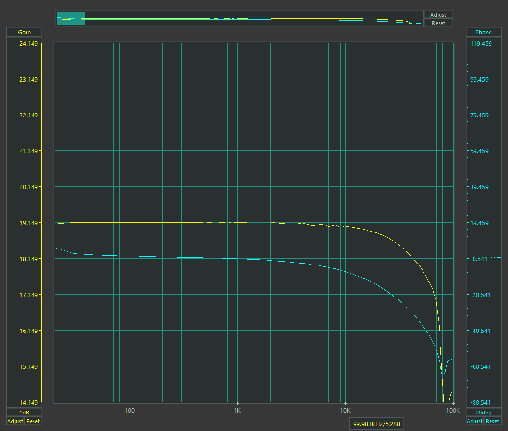
In this figure we see a low-quality output transformer. In the yellow graph the bandwidth is shown, with a scale of 5 dB per division, while in blue the phase shift is shown, with a scale of 50 degrees per division:
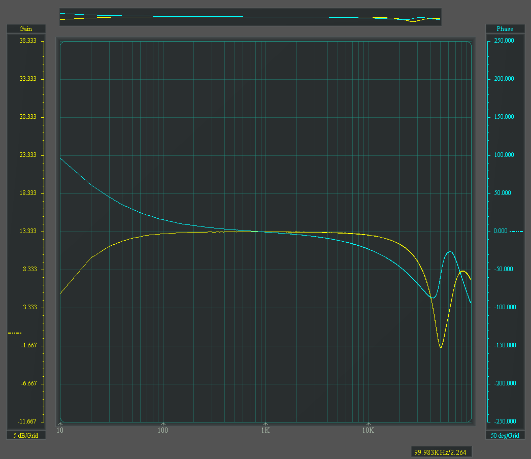
A) We can see a bandwidth of about 15 Hz – 35 kHz at -5 dB. The phase shift already starts very noticeably at the low end, reaches about 100 degrees up to 1 kHz and then continues to worsen gradually toward the high end.
Now let us see below how a wide-band transformer produced by SB-LAB behaves, of the same type and for the same valve:
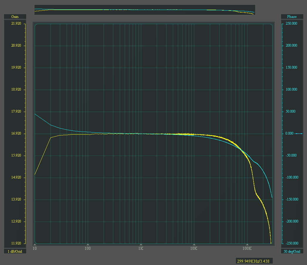
B) Here we see a bandwidth of about 10 Hz at -2 dB and 180 kHz at -3 dB. The low-frequency phase shift already settles around 100 Hz, remains much more controlled in the audio range and reaches 50 degrees only at very high frequencies, around 100 kHz.
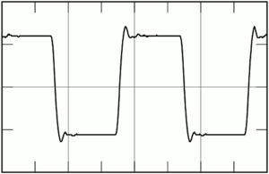
A transformer with very wide bandwidth also tends to have lower parasitic capacitances and better transient behavior. This can be seen clearly by observing the square wave response. Ringing is a damped oscillation that appears on the signal edges, linked to the resonances of the transformer.
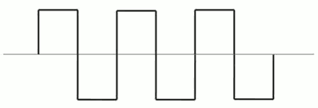
The following are two examples of typical ringing in medium-quality transformers:
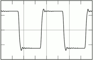
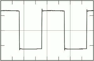
The following image instead shows the ringing of a very high-quality, high-bandwidth transformer:
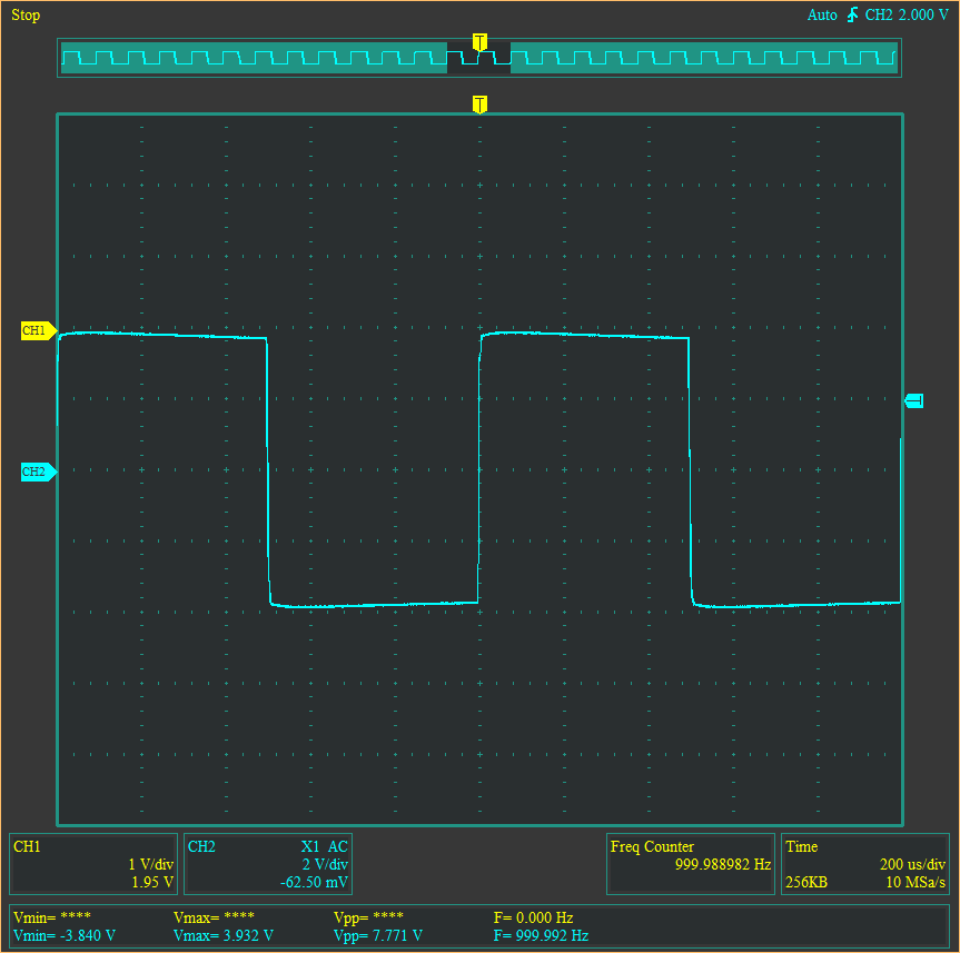
Here, for example, is a 1 kHz square wave from an SB-LAB transformer:
And the same square wave produced by a transformer from a cheap made-in-China amplifier:
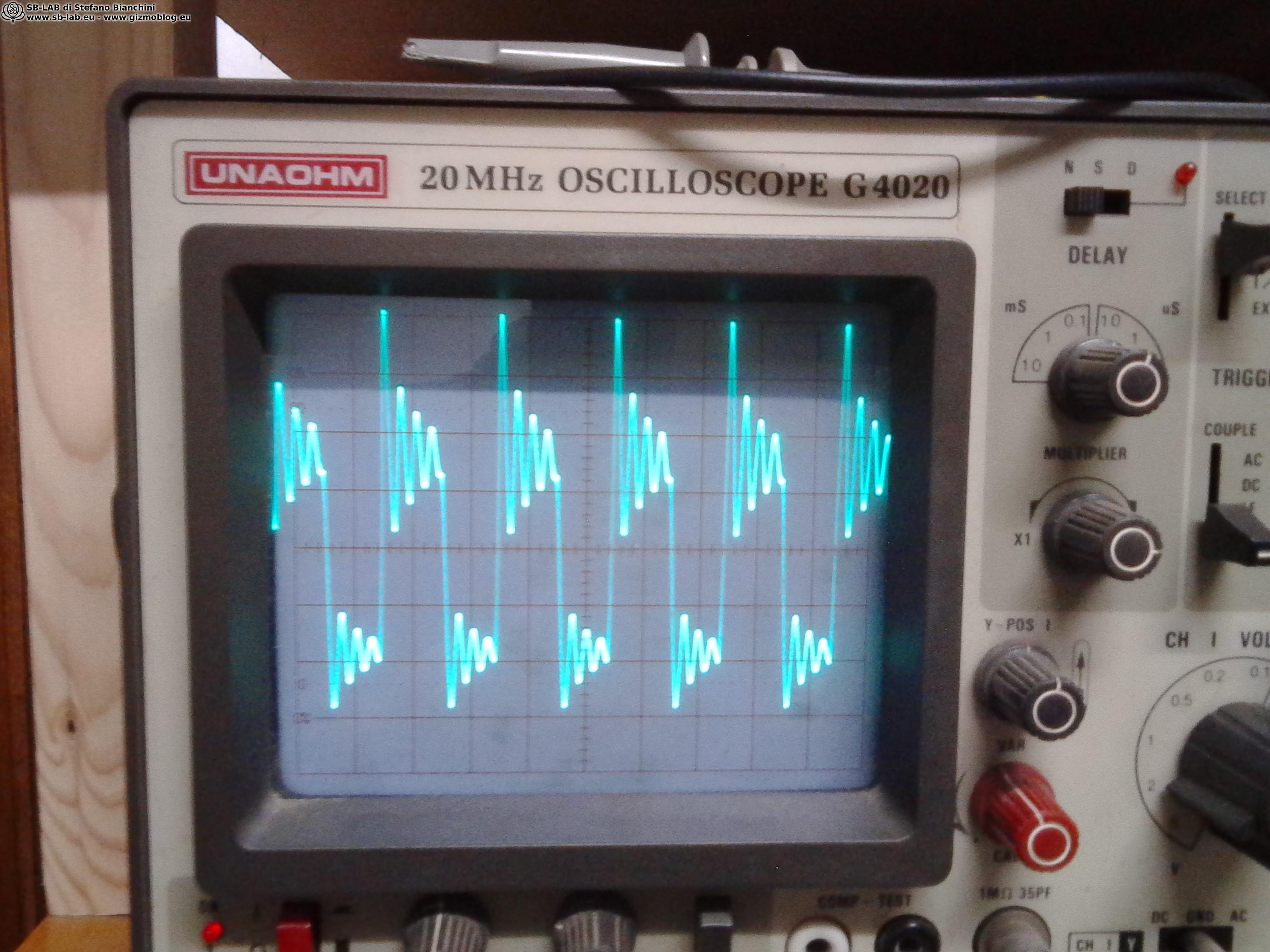
Naturally, when listening, we do not reproduce square waves, but music. Square waves are used to highlight defects that may go unnoticed with a single sine wave. If a transformer shows ringing, overshoot or deformed edges, those problems do not disappear when listening to music: they appear as a loss of cleanliness, less precision on transients and a more confused sound.
A Good Reason to Oversize Cores and Use EI Laminations Instead of Other Cores
Another criticism I have received concerns the size of my transformers. I have already talked about this in the past, but it is worth clarifying one point: the transformer core mainly affects the low and middle part of the audio band, where magnetic flux is more relevant. To obtain good behavior, it is important for the core to work at low induction, far from the most non-linear areas of the hysteresis curve.
A small core, pushed to the limit, can introduce unwanted harmonics and make the sound dirtier. A larger core, used properly, works in a more relaxed and linear way. This is one of the reasons why I often prefer transformers that appear oversized.
I willingly use EI laminated cores, even though some people look down on them because they consider them common or less “noble” than toroidal, double C or high-permeability materials. In reality, EI laminations, if used well, have important advantages: they are predictable, tolerate certain working conditions better and have a more progressive saturation curve.
Toroidal cores, for example, can be very efficient, but in an audio output transformer they are not always the best choice. They can suffer more from unwanted DC currents, bias imbalances in push-pull stages or non-ideal conditions. In single-ended transformers, where DC current is intentional, the choice of core and air gap becomes even more critical.
There is no perfect core in absolute terms. There is the core suitable for that transformer, that valve and that circuit. My choice of EI laminations does not come from economy or habit, but from practical tests and measured results.
Beware of Those Who Declare False or Incomplete Data
Some questionable practices used by manufacturers who do not pay enough attention to the quality of their work.
Very often, in price lists, you see bandwidths declared with values that are too perfect: 20 Hz – 20 kHz, 30 Hz – 30 kHz, 10 Hz – 50 kHz, always round and always the same. In real production, it is difficult for different transformers to have exactly such clean limits. One may reach 29 kHz, another 34 kHz, and another may have a different behavior at the low end. Numbers that are too neat and repeated too often should always be read with caution.
Even more important is attenuation. A declared bandwidth without indicating the dB means nothing. 30 Hz – 30 kHz at -1 dB is one thing; 30 Hz – 30 kHz at -6 dB is another. The measurement power is also fundamental, because a transformer can behave well at low level and worsen when real power is demanded from it.
Showing only square waves is not enough either. Square wave response is useful because it highlights ringing, overshoot and transient limitations, but it does not replace a complete measurement of frequency response, phase, distortion and behavior on the intended load.
In conclusion, an output transformer is not judged by an isolated number, a marketing phrase or a photo of the oscilloscope. It is judged as a whole: correctly declared bandwidth, attenuation, measurement conditions, phase behavior, square wave response, coupling with the valve and real results in the circuit.
Extended bandwidth is not for giving concerts to bats. It is used to make the transformer work better inside the audible band, reducing attenuation, phase shifts, resonances and defects that the ear can definitely hear. A good transformer must not impress with invented numbers: it must measure well, work well and sound good.